
Computer tomographic method and computer tomographic (CT) instrument

A computer and X-ray technology, applied in the field of computed tomography, can solve the problems such as the inability to fully utilize the radiation dose of the detector area, and the inability of the image plane to adapt to the spiral orbit.

Inactive Publication Date: 2002-12-18
SIEMENS AG
View PDF1 Cites 1 Cited by
  • Summary
  • Abstract
  • Description
  • Claims
  • Application Information

AI Technical Summary

Problems solved by technology

But when the pitch is less than the maximum pitch p max When , the detector area and the radiation dose used to obtain the image (detector utilization and radiation dose utilization) cannot be fully utilized, because although a helical segment greater than 180° plus a sector angle or a cone angle A given cross-sectional slice of the object perpendicular to the system axis z is scanned, but in the method known from US 5 802 134 for smaller than the maximum pitch p max The pitch p only utilizes the helical section of 180° plus the cone angle. Since a longer helical section cannot be used, the image plane cannot fully adapt to the helical track

Method used


Image

  • Computer tomographic method and computer tomographic (CT) instrument
  • Computer tomographic method and computer tomographic (CT) instrument
  • Computer tomographic method and computer tomographic (CT) instrument

Examples


Embodiment Construction

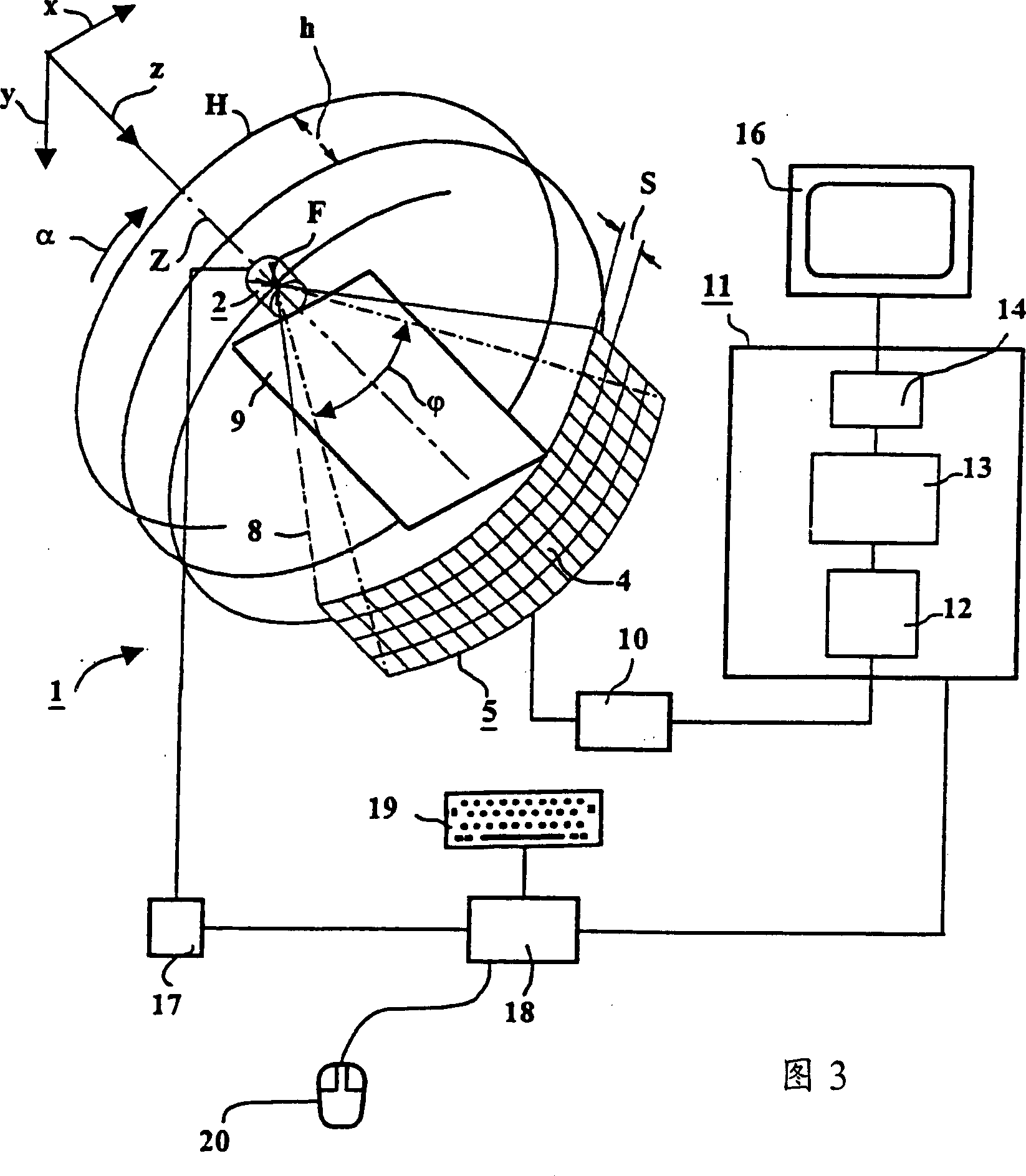
[0047] Figure 3 and Figure 4 Shown is a third-generation multislice CT apparatus suitable for implementing the method according to the invention. The measuring device denoted by 1 as a whole has: an X-ray source denoted by 2 and a ray diaphragm 3 ( Figure 4 ); A multi-faceted array composed of multiple rows and multiple columns of detector elements (one of which is represented by 4 in Figure 3), namely the detector array 5, a ray diaphragm 6 ( Figure 4 ). The X-ray source 2 with the ray stop 3 is on one side, and the detector array 5 with the ray stop 6 is on the other side to Figure 4 The way shown in is arranged opposite to each other on a rotating frame 7 which is also referred to as a gantry in the following: that is, during the operation of the CT instrument, the X-ray source 2 emits rays and is condensed by the adjustable ray diaphragm 3 An X-ray beam having a pyramid shape whose edge rays are denoted by 8 is incident on the detector array 5. In this case, the ray diaphr...


PUM


Abstract

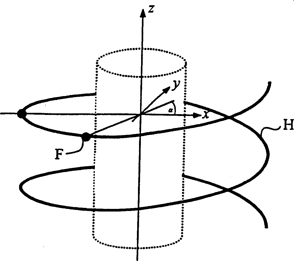
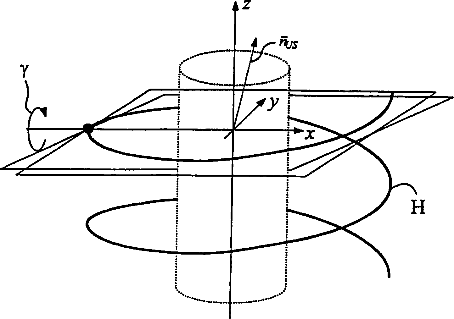
The present invention relates to a computer tomography method and a computer tomography (CT) apparatus, wherein: a) an object is scanned with a cone-shaped ray beam emitted from a focal point, and a matrix detection An array of detectors detects the beam of rays, for which the focal point moves relative to the object on a helical trajectory, the central axis of which corresponds to the axis of the system, wherein the array of detectors outputs output data corresponding to the received rays, b) An image with an inclined image plane is reproduced from the output data provided during the movement of the focal point on the helical track, wherein the image plane is inclined with respect to the system axis by an inclination angle γ to a first axis intersecting at right angles to the system axis, and to both A second axis which intersects the first axis at right angles to the system axis is inclined by an inclination δ.

Description

Technical field [0001] The invention relates to a computer tomography method, which has the following steps: scanning an object with a cone-shaped ray beam emitted from a focal point, and detecting the ray beam with a matrix detector array, for which the focal point Relative to the object, it moves around the system axis on a spiral orbit, where the detector array outputs output data corresponding to the received rays; according to the output data provided during the movement of the focus on the spiral orbit, an image with a tilt relative to the system axis is reproduced The image of the face. In addition, the present invention also relates to a computer tomography (CT) apparatus, which has: a radiation source, which emits a cone-shaped beam from its focal point; and a matrix detector array for detecting the beam , Wherein the detector array outputs output data corresponding to the received rays; components used to generate relative motion between the ray source and the detector a...

Claims


Application Information

Patent Timeline
Patent Type & Authority Applications(China)
IPC IPC(8): A61B6/03
CPCA61B6/032A61B6/4085A61B6/027Y10S378/901
Inventor 赫伯特·布鲁德托马斯·弗洛尔马克·卡切尔里斯斯蒂芬·沙勒卡尔·斯蒂尔斯托弗
Owner SIEMENS AG
Learn More