Surface acoustic wave device
A surface elastic wave and substrate technology, applied in the direction of electrical components, impedance networks, etc., can solve the problems of SAW speed increase, frequency temperature coefficient increase and decrease, etc., and achieve the effect of large electrical mechanical coupling coefficient and small SAW speed
- Summary
- Abstract
- Description
- Claims
- Application Information
AI Technical Summary
Problems solved by technology
Method used
Image
Examples
no. 1 example
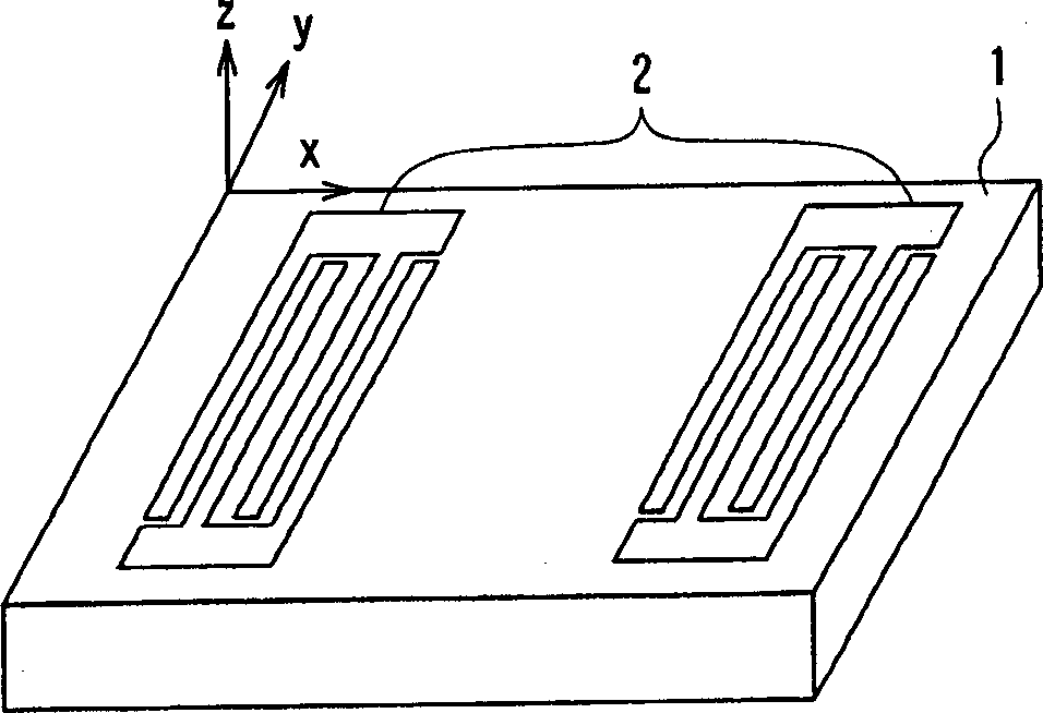
[0054] In the first embodiment, a cut substrate 1 of (0°, 140°, 23°) represented by Euler angles included in the first region is prepared to fabricate a surface acoustic wave filter. In this filter, the number of pairs of interdigitated electrodes 2 is 100 pairs, the opening length (the length of the intersecting portion) is 80λ (λ is the wavelength of the surface acoustic wave), and as the film thickness h of the electrode and the wavelength of the surface acoustic wave The normalized film thickness h / λ of the λ ratio is 0.02.
[0055] Figure 4 It is the relationship between the normalized frequency and the conversion loss, which is the frequency characteristic of the above-mentioned filter obtained in the calculation. exist Figure 4 In , the solid line indicates the characteristics in the forward direction, and the dashed line indicates the characteristics in the reverse direction. as from Figure 4 As can be seen, there is a large difference in the conversion loss bet...
no. 2 example
[0059] In the second embodiment, using the cut substrate 1 represented by Euler angles (0°, 140°, 23°) contained in the first region, the Figure 5 The measurement device including the surface acoustic wave filter is shown, and the transmission characteristics of the device are measured. Figure 5 The shown measurement device includes: a transmitting electrode 2A provided on a substrate 1 as an interdigital electrode, and two receiving electrodes 2B arranged on both sides of the transmitting electrode 2A in the propagation direction of a surface acoustic wave.
[0060] exist Figure 5 In the measurement device shown, the electrode period (λ) is 30 μm, the number of pairs of transmitting electrodes 2A is 100.5 pairs, the opening length (the length of the intersection portion) is 30λ, and the number of pairs of receiving electrodes 2B is 20.5 pairs. In this example, a measurement device with a normalized film thickness h / λ of 0.01 and a measurement device with a normalized film...
no. 3 example
[0063] In the third embodiment, using the cut substrate 1 represented by Euler angles (0°, 140°, 25°) included in the first area, a Figure 5 The measurement device including the surface acoustic wave filter is shown, and the transmission characteristics of the device are measured. Other conditions of the measurement device are the same as those of the second example.
[0064] Figure 8 It shows the results of measuring the transmission characteristics of a measurement device with a normalized film thickness h / λ of 0.01, that is, the relationship between frequency and insertion loss. and, Figure 9 It shows the results of measuring the relationship between frequency and insertion loss, which is the transmission characteristic of a measurement device whose normalized film thickness h / λ is 0.02. exist Figure 8 and Figure 9 In , the solid line indicates the characteristics in the forward direction, and the dashed line indicates the characteristics in the reverse direction....
PUM
 Abstract
Description
Claims
Application Information
 - R&D Engineer
- R&D Manager
- IP Professional
- Industry Leading Data Capabilities
- Powerful AI technology
- Patent DNA Extraction
Browse by: Latest US Patents, China's latest patents, Technical Efficacy Thesaurus, Application Domain, Technology Topic, Popular Technical Reports.
© 2024 PatSnap. All rights reserved.Legal|Privacy policy|Modern Slavery Act Transparency Statement|Sitemap|About US| Contact US: help@patsnap.com


