
Hydraulic oil soot exhauster with frequency-varying displacement-type speed control

A technology of volumetric speed regulation and oil pumping unit, which is applied in the direction of transmission control, mechanical equipment, and components with teeth, etc. It can solve the problem of not fully utilizing the efficiency of the motor and hydraulic pump, the inability of the motor to automatically adjust the output power, and oil pumping. The energy-saving effect of the computer is not obvious, and the software and hardware resources are abundant, the energy-saving effect is remarkable, and the energy-saving effect is obvious.

Inactive Publication Date: 2002-06-12
ZHEJIANG UNIV
View PDF0 Cites 5 Cited by
  • Summary
  • Abstract
  • Description
  • Claims
  • Application Information

AI Technical Summary

Problems solved by technology

Due to its huge balance weight, reducer, four-link mechanism and belt drive, it consumes a lot of energy during operation
In addition, the motor cannot automatically adjust its output power according to the load change of the pumping unit’s up and down strokes, so the system efficiency of the pumping unit is very low
[0005] 2) It is impossible to realize automatic control according to the requirements of complex and changeable oil well conditions
In recent years, as my country's oilfields increasingly need long-stroke, low-stroke pumping units to increase fluid production, people have studied a variety of energy-saving hydraulic pumping units, which are improving oil pumping Some progress has been made in improving the efficiency of the pumping unit, but because the designed hydraulic system is only based on how to recover the energy of the downstroke of the pumping unit, it has not fully utilized the power of the motor and hydraulic pump. At the same time, the self-adaptive ability of the pumping unit is poor, resulting in low system efficiency, and the energy-saving effect of the pumping unit is not obvious, so it has not been effectively promoted

Method used


Image

  • Hydraulic oil soot exhauster with frequency-varying displacement-type speed control
  • Hydraulic oil soot exhauster with frequency-varying displacement-type speed control
  • Hydraulic oil soot exhauster with frequency-varying displacement-type speed control

Examples


Embodiment Construction

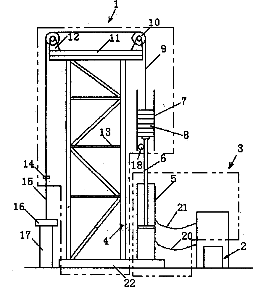
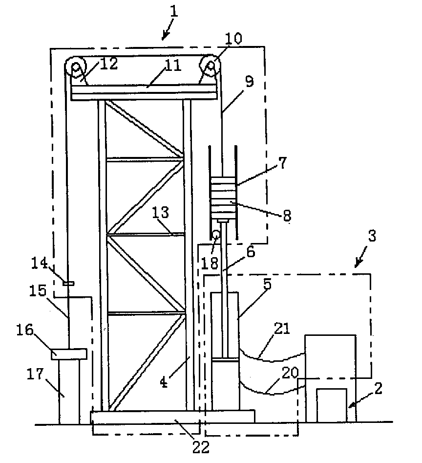
[0029] Such as figure 1 , figure 2 As shown, the hydraulic pumping unit controlled by frequency conversion volume speed regulation includes a mechanical device 1, a detection control device 2, and a hydraulic control device 3, wherein:

[0030] 1) In the mechanical device 1, the polished rod 15 of the pumping unit is directly connected to the piston rod 6 of the hydraulic cylinder 5 through the steel wire rope 9 mounted on the rollers 10 at both ends of the upper base plate 11 and the counterweight 8 mounted in the guide rail 7;

[0031] 2) Detection and control device 2: including a speed measuring photoelectric encoder 26, an AC vector frequency converter 28, a control detection unit 29, and a speed position sensor 18; the AC vector frequency converter 28 is connected to the motor 25 through the speed measuring photoelectric encoder 26, and the AC vector 28 is also connected with the motor 25, and the control detection unit 29 is connected with the AC vector frequency conv...


PUM


Abstract

A hydraulic pumping unit is composed of mechanical facilities, detecting controller and hydraulic controller. It features that the voltage conversion and frequency conversion are used to control the speed of motor and in turn the speed of pumping unit, and a mechanical counter weight is used to reduce the power needed by pumping unit itself and effectively use the potential energy of downward stroke. Its advantages include optimal speed curve and efficiency, stepless speed and stroke regulation, and overload, off-load, overcurrent and instantaneous stall protections.

Description

technical field [0001] The invention relates to a device for extracting fluid from a well, in particular to a hydraulic pumping unit suitable for oil extraction on land. Background technique [0002] Rod pumping unit is a kind of mechanical pumping equipment commonly used in oilfield development at present, which is divided into beam pumping unit and beamless pumping unit. Beam pumping units have been widely used in oil fields due to their durability, reliable components, and easy maintenance. However, during the long-term use of the beam pumping unit, many problems have been exposed: [0003] 1) Large installed power, high energy consumption and low efficiency [0004] The pumping unit is bulky, complex in structure and large in installed power. At present, the average installed capacity of a pumping unit in onshore oilfields is above 32.6KW, and the annual power consumption of rod pumping units in onshore oilfields in my country is about 6.76 b...

Claims


Application Information

Patent Timeline
Patent Type & Authority Applications(China)
IPC IPC(8): E21B43/00F16H61/47
Inventor 徐兵杨华勇欧阳小平
Owner ZHEJIANG UNIV
Learn More