
Control device of intelligent lamp, and illuminance control method

A technology for control devices and lamps, which is applied in the field of wireless communication, can solve the problems of wasting electric energy, wasting electric energy, reducing the brightness value of intelligent lamps, etc., and achieves the effects of saving electric energy, saving energy, and reducing errors

Inactive Publication Date: 2019-04-02
西安非凡士智能科技有限公司
View PDF2 Cites 0 Cited by
  • Summary
  • Abstract
  • Description
  • Claims
  • Application Information

AI Technical Summary

Problems solved by technology

[0003] The brightness value of the existing smart lamps is fixed, that is, the smart lamps are running at full load at any time. Even in the daytime, when the smart lamps detect that someone is passing by, they will still light up, resulting in a large amount of power waste.
Therefore, the smart lamps are generally turned off during the day and turned on at night, or set to reduce the brightness value of the smart lamps when they are working, but this will cause the brightness value of the smart lamps at night to fail to meet the conditions of use.
[0004] In view of the existing technical problems, it is necessary to set up a control device for intelligent lamps, so as to solve the problem of waste of electric energy in existing intelligent lamps

Method used


Image

  • Control device of intelligent lamp, and illuminance control method
  • Control device of intelligent lamp, and illuminance control method
  • Control device of intelligent lamp, and illuminance control method

Examples


Embodiment Construction

[0037] The present invention will be further described in detail below in conjunction with the accompanying drawings, which are explanations rather than limitations of the present invention.

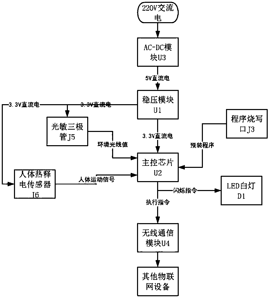
[0038] Such as figure 1 As shown, a control device for an intelligent lamp includes an AC-DC module U3, a voltage stabilizing module U1, a main control chip U2, a wireless communication module U4, a phototransistor J5 and a human body pyroelectric sensor J6.

[0039] Among them, the input end of the AC-DC module U3 is connected to 220V AC, the output end is connected to the voltage stabilizing module U1, and the voltage stabilizing module U1 is respectively connected to the main control chip U2, the photosensitive transistor J5 and the human body pyroelectric sensor J6, and the main control chip U2 is connected with the smart lamp through the wireless communication module U4. The phototransistor J5 and the human body pyroelectric sensor J6 are signal-connected to the main control chip U...


PUM


Abstract

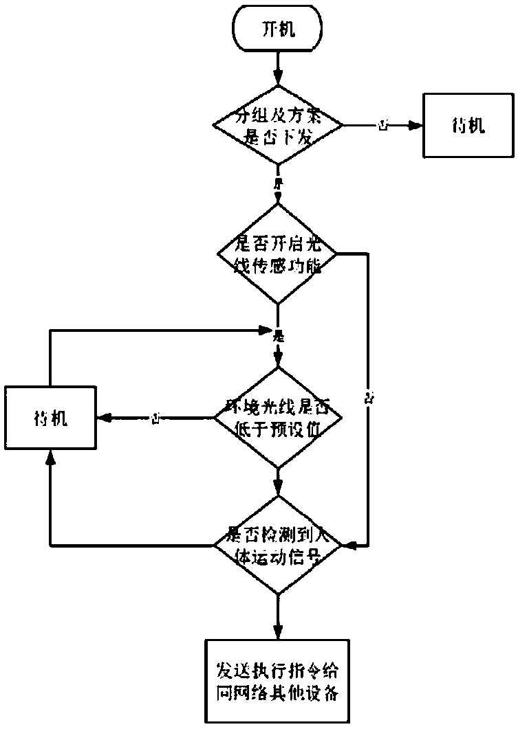
The invention discloses a control device of an intelligent lamp. The input end of an AC-DC module U3 is electrically connected with a 220V alternating current, and the output end is connected with a voltage stabilization module U1; the voltage stabilization module U1 is connected with a main control chip U2 and a photosensitive triode J5 separately; a wireless communication module U4 is connectedwith the main control chip U2; the photosensitive triode J5 is in signal interaction with the main control chip U2; and the main control chip U2 is used for receiving the illuminance value collected by the photosensitive triode J5, comparing with the set working illuminance value and outputting the working power of the corresponding intelligent lamp. By virtue of the control device of the intelligent lamp, the intensity of ambient light is collected, and the illuminance value is accurately analyzed; and the main control chip outputs the working power of the intelligent lamp according to the illuminance value, so that the environment light can be compensated, the ambient light can reach the use standard, and the purpose of saving energy is achieved.

Description

technical field [0001] The invention relates to the field of wireless communication, in particular to a control device and a control method for an intelligent lamp. Background technique [0002] With the development of computer technology and communication technology, the use of smart lamps in public places is becoming more and more extensive. Now the smart lamps that combine light control and voice control are mainly used. , so as to light the lamps to illuminate pedestrians. [0003] The brightness value of the existing smart lamps is fixed, that is, the smart lamps are running at full load at any time. Even in the daytime, when the smart lamps detect that someone is passing by, they will still light up, resulting in a large amount of waste of electric energy. Therefore, the smart lamps are generally turned off during the day and turned on again at night, or set to reduce the brightness value of the smart lamps when they are working, but this will cause the brightness val...

Claims


Application Information

Patent Timeline
Patent Type & Authority Applications(China)
IPC IPC(8): H05B37/02
CPCH05B47/10H05B47/105H05B47/11H05B47/19
Inventor 赵瓅晔靳慧康戚平礼
Owner 西安非凡士智能科技有限公司
Learn More