Electrically controlled lock
An electric control lock and electric control technology, applied in the field of electric control locks, can solve the problems of reduced safety and inability to energize for a long time, and achieve the effects of easy production and assembly, compact structure and good working stability.
- Summary
- Abstract
- Description
- Claims
- Application Information
AI Technical Summary
Problems solved by technology
Method used
Image

Examples
Embodiment 1
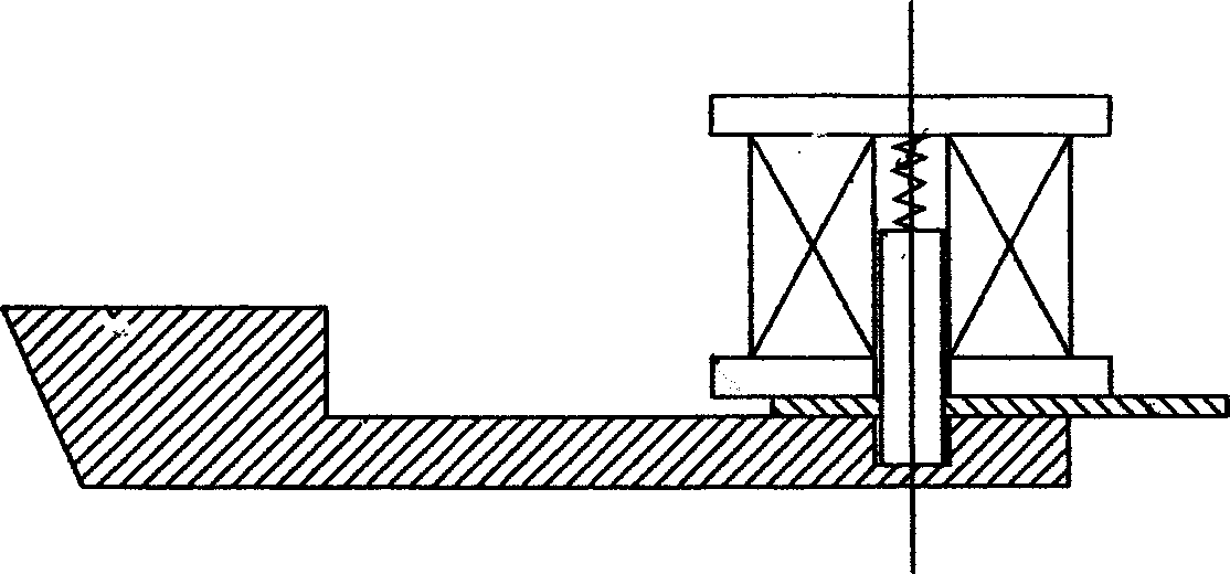
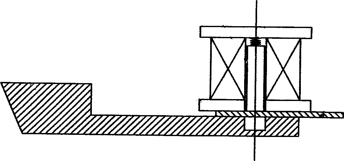
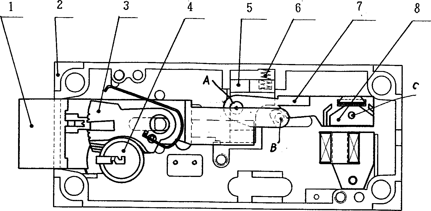
[0025] Example 1, such as Figure 3-7 As shown, the electric control lock includes a housing 2 and a deadbolt 1. A deadbolt hole is opened on one side of the housing 2, and a deadbolt 1 is installed through the deadbolt hole. The main body of the deadbolt is rectangular, roughly in the middle There is a positioning groove 11 in the position, and a positioning column is integrally formed on the shell wall correspondingly, which also becomes the fixing column of the locking plate group. Shrapnel, the other end of the shrapnel is bent, and it is supported on the upper wall of the housing. There is a slot in the front of the lock piece 3, and a guide piece is formed on the back of the tongue of the lock tongue to cooperate with the slot on the lock piece 3. The bottom of the sheet group is fixed with a lock core 4 through a positioning hole, and the lock core cooperates with the lock plate, so that they form a mechanical locking mechanism that drives the dead bolt to perform teles...
Embodiment 2
[0027] Example 2, such as Figure 9-14 As shown, the electric control lock includes a housing and a deadbolt 1'. A deadbolt hole is opened on one side of the casing, and a deadbolt is installed through the deadbolt hole. The main body of the deadbolt is rectangular, and the rear side of the deadbolt is A dial column 5' is formed, and correspondingly, the rear punch 8' has a guide groove 6' in the lower part of the middle. Acting as a lever for changing the fulcrum, there is another front punch 3', which has a socket 4' at the upper middle position, and a column on the side of the rear punch correspondingly, and the front The punching piece is connected with the back punching piece, and their lower parts are all opened with hook pins, and the spring 7' is used to pull up the hook pins, and the front part of the front punching piece also has a slot, which cooperates with the plug 2' on the side of the deadbolt. The shell below the front punch has a stop post 11' to limit the fr...
PUM
 Abstract
Description
Claims
Application Information
 - Generate Ideas
- Intellectual Property
- Life Sciences
- Materials
- Tech Scout
- Unparalleled Data Quality
- Higher Quality Content
- 60% Fewer Hallucinations
Browse by: Latest US Patents, China's latest patents, Technical Efficacy Thesaurus, Application Domain, Technology Topic, Popular Technical Reports.
© 2025 PatSnap. All rights reserved.Legal|Privacy policy|Modern Slavery Act Transparency Statement|Sitemap|About US| Contact US: help@patsnap.com