Column supported underground continuous wall

An underground diaphragm wall and basement technology, applied in underwater structures, water conservancy projects, artificial islands, etc., can solve the problems that affect the development of reverse technology, increase the project cost, and increase the cost of entering the rock, etc., to achieve expansion Effectively use the area, save the enclosure wall, and reduce the effect of high cost

Inactive Publication Date: 2007-08-22
陈星 +14
View PDF4 Cites 0 Cited by
  • Summary
  • Abstract
  • Description
  • Claims
  • Application Information

AI Technical Summary

Problems solved by technology

[0005] (1) Since the construction of the underground diaphragm wall requires large-scale special machinery, the groove section is generally formed by drilling and punching, and the wall is protected by mud, so the construction cost is relatively high
[0006] (2) It is difficult for the diaphragm wall to excavate into grooves in hard soil and rock layers, especially when the rock layers are buried shallowly, that is, when the geological conditions are good, and in the case of a multi-layer basement, the increased cost of entering the rock is very large. Larger increase in project cost
[0007] (3) Due to the close connection between the underground diaphragm wall and the reverse method technology, the high cost of the diaphragm wall directly affects the application and promotion of the basement reverse method technology. How to ensure the safety of the foundation pit project can shorten the construction period and at the same time control the project cost , has become a key issue affecting the development of reverse technology

Method used


Image

  • Column supported underground continuous wall
  • Column supported underground continuous wall
  • Column supported underground continuous wall

Examples


Embodiment 1

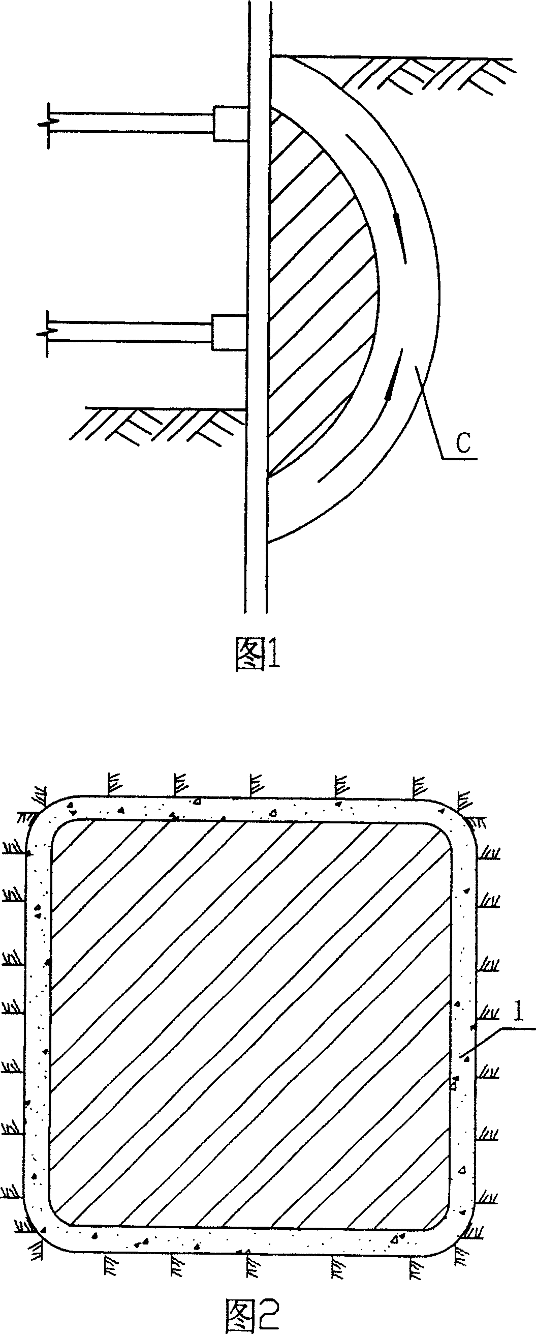
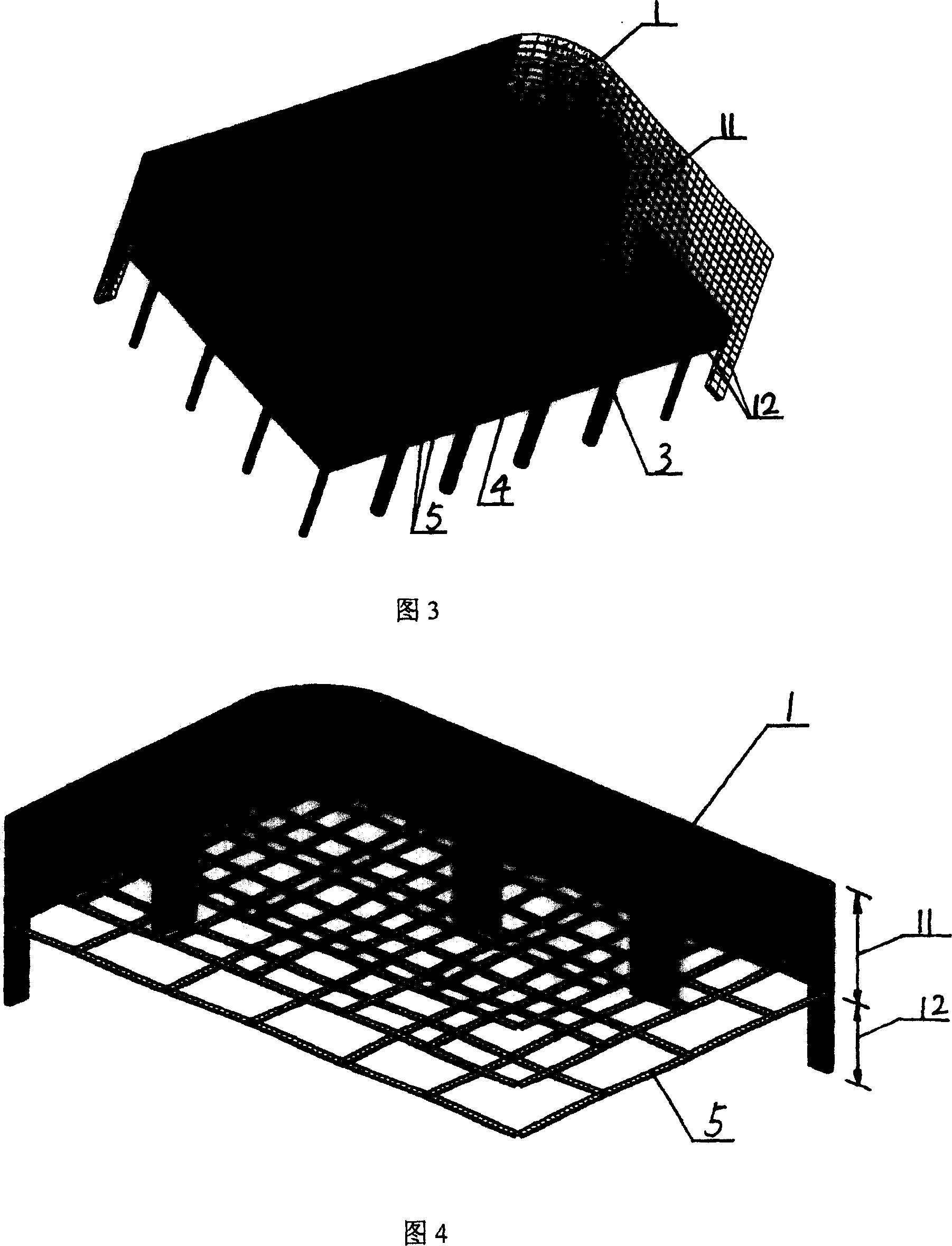
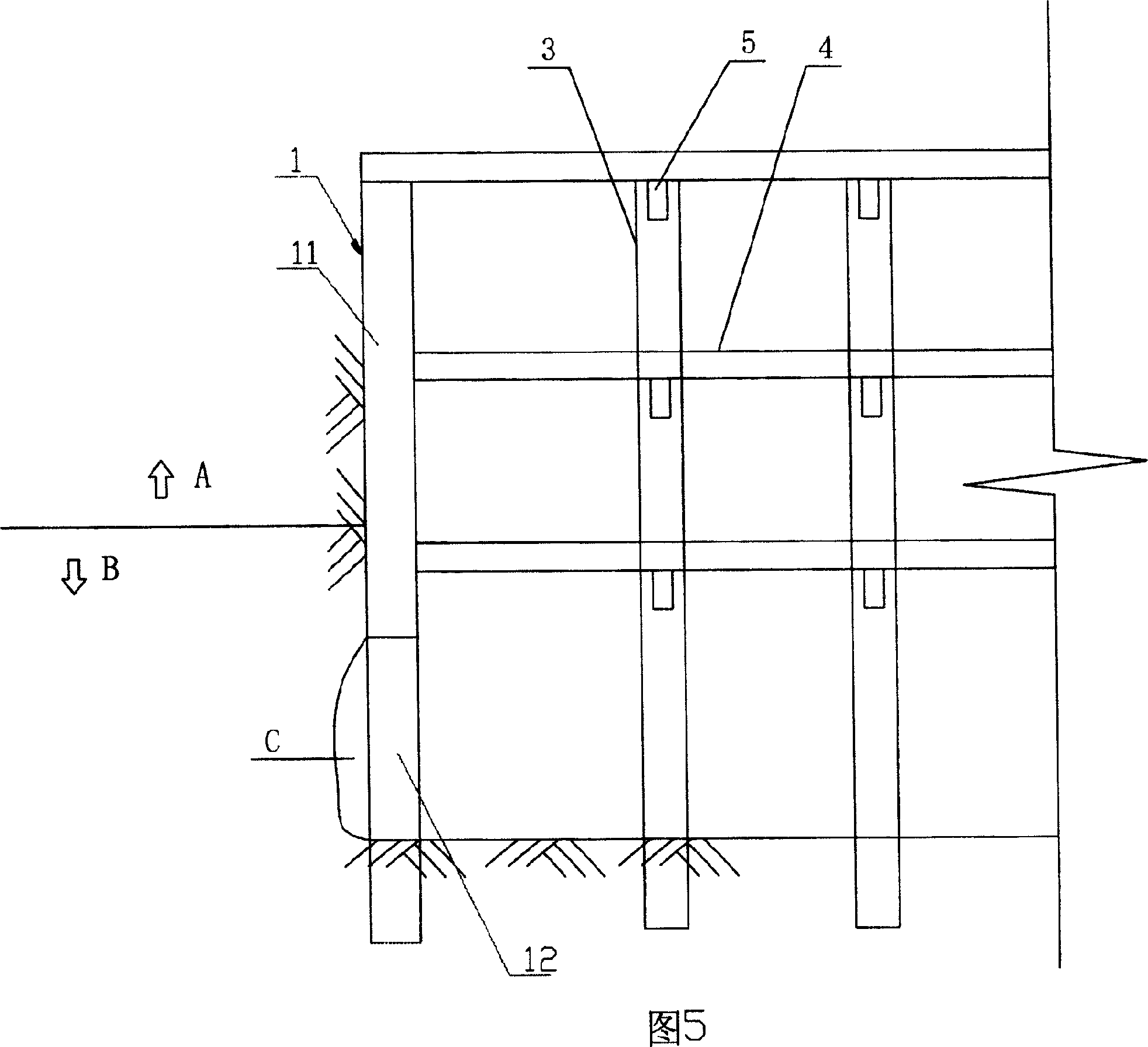
[0039] As shown in Figures 2 to 5, a column-supported underground diaphragm wall constructed by the reverse method of the basement is one of the embodiments of the present invention. The wall body 11 and the deep wall body 12 are formed. The shallow wall body 11 is located on the upper part of the underground diaphragm wall 1 and has a common underground diaphragm wall body structure. A closed wall body is formed along the periphery of the basement, covering all the bad soil A, It is used for soil retaining, water retaining and impermeability during basement reverse construction. The basement superstructure formed by the combination of the shallow wall and the floor 4, beams 5 and columns 3 has huge lateral stiffness, and the lateral earth pressure displacement is small, which can be regarded as a fixed horizontal support for the soil.

[0040] The deep wall body 12 extends from the bottom of the shallow wall body to the rock socket, using the completed basement superstructure...

Embodiment 2

[0042] The column-supported underground diaphragm wall shown in Figures 6 to 10 is the second embodiment of the present invention. The difference from the previous example is that the wall between the two adjacent column-supported walls of the deep wall 12 of the underground continuous wall is different. The spacing is 20 meters, and the shotcrete support composite member 2 is set in this spacing, that is, shotcrete support is used between adjacent column support walls, that is, soil nails 21 are used to fix the metal mesh on the side wall of the foundation pit The concrete is then sprayed to form a thin wall structure with a certain retaining effect. In addition, an anchor rod 22 is also driven into the lower part of the shallow wall to further strengthen the horizontal support of the shallow wall.

[0043] As shown in Figures 6, 8, and 9, the shallow wall of the underground diaphragm wall is formed by constructing the entire underground diaphragm wall into multiple unit widt...


PUM


Abstract

The invention relates to a post underground continuous wall which is constructed via basement reverse method. It comprises: the underground wall along the basement, which is formed by shallow wall and deep wall, while the shallow is at the upper part of underground continuous wall, with general structure to form the closed wall as baffling sand, water and filtration; and said deep wall is under the shallow wall which is a post support wall whose rock embedded sections are distantly arranged, to support the shallow wall and be used as the vertical support element, to effectively control the vertical distortion of upper part pf underground continuous wall. The shallow wall can reduce the height of underground continuous wall and the deep wall can reduce the number of rock-embedded sections with high cost and hard construction. The invention can reduce the cost and shorten the construction time.

Description

technical field [0001] The invention relates to an underground continuous wall of a building, in particular to a column-supported underground continuous wall constructed by a basement inverse method. Background technique [0002] The underground diaphragm wall of a building is a foundation pit support system of a water-retaining and soil-retaining structure applied to the construction of the reverse-method basement structure. One of the most commonly used support techniques. [0003] In the prior art, the multi-storey basement and other multi-storey underground structures of high-rise buildings are often constructed by the reverse method, that is, the floor structure of the basement, including beams, slabs, columns, etc., and the external wall structure are used as the level of the foundation pit envelope. For the support system and the enclosure system, the reverse method takes the base layer as the boundary, the basement of each layer below the base layer is constructed f...

Claims


Application Information

Patent Timeline
Patent Type & Authority Patents(China)
IPC IPC(8): E02D29/00E02D29/02E02D27/10
Inventor 陈星蔡健罗赤宇孙礼军马天洲叶群英林扑强向前吴建营徐静何锦超王金锋莫海鸿陈颖陈宗弼
Owner 陈星
Why Eureka
Try Eureka