Shunt-feed omnidirectional antenna array

An omnidirectional antenna and array technology, which is applied in the directions of antenna arrays, antenna arrays that are energized separately, antennas, etc., can solve the problems of destroying omnidirectional radiation characteristics of omnidirectional antennas, feeding network shading cannot be eliminated, difficulties, etc., and achieve compact structure , flexible layout, and wide-band characteristics

Active Publication Date: 2007-07-11
南京易太可通信技术有限公司
View PDF1 Cites 0 Cited by
  • Summary
  • Abstract
  • Description
  • Claims
  • Application Information

AI Technical Summary

Problems solved by technology

For a single omnidirectional antenna, it is more difficult to realize parallel feed. The main reason is that the shading of the feed network cannot be eliminated, so zero points or notches are formed on the azimuth pattern of the omnidirectional antenna, which destroys the omnidirectional antenna. Omnidirectional Radiation Characteristics of the Antenna

Method used


Image

  • Shunt-feed omnidirectional antenna array
  • Shunt-feed omnidirectional antenna array
  • Shunt-feed omnidirectional antenna array

Examples


Embodiment 1

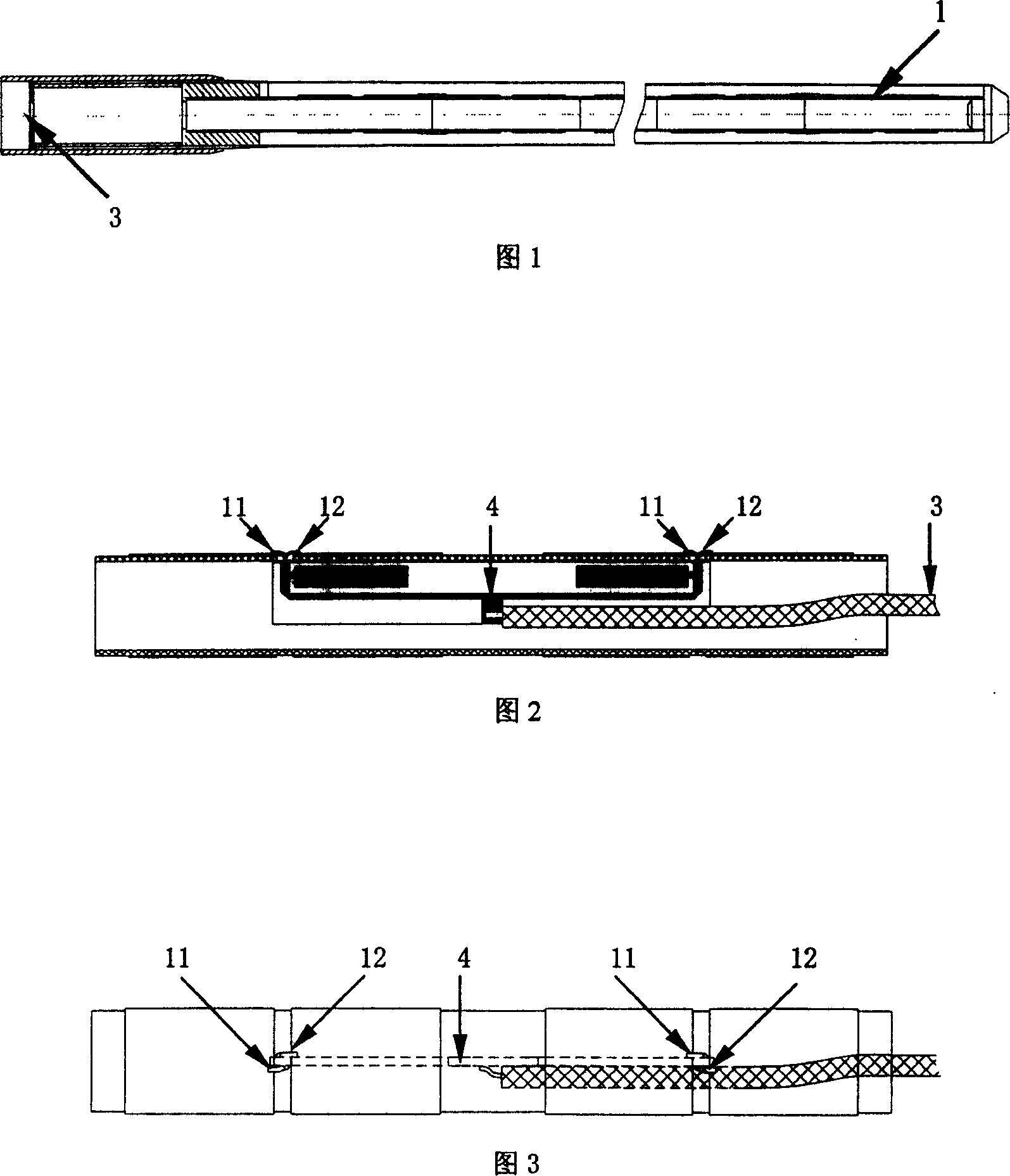
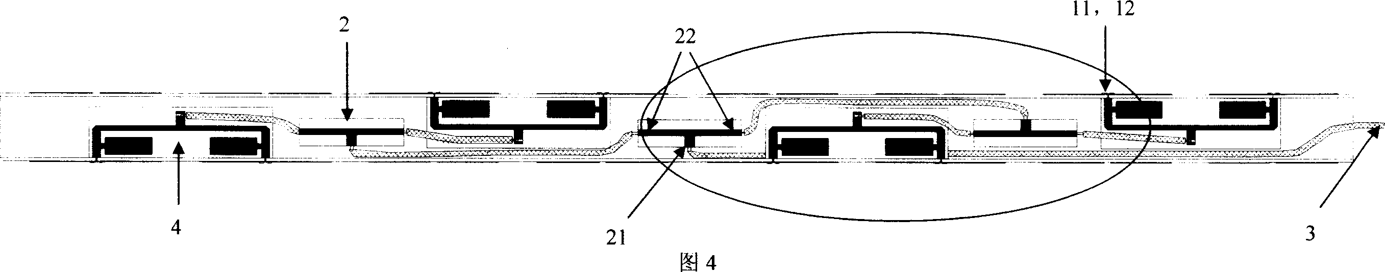
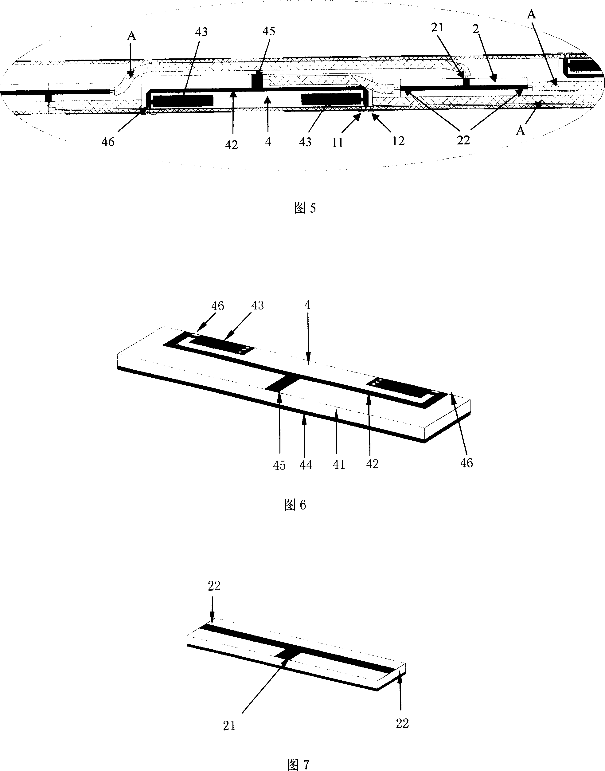
[0020] Embodiment 1 A parallel-fed omnidirectional antenna array suitable for broadband work, including at least two hollow elements 1, with an antenna input port 3 at the bottom of the antenna, and a feed circuit 4 inside the hollow elements 1 , the input port 45 of the feed circuit 4 is connected to the antenna input port 3, the feed circuit 4 is composed of a microstrip dielectric substrate 41, a power divider 42, a microstrip short circuit 43 and a microstrip ground plane 44, the microstrip ground plane 44 is located on the surface of the microstrip dielectric substrate 41, the power divider 42 and the microstrip short-circuit line 43 are located on the other surface of the microstrip dielectric substrate 41, the microstrip terminal of the output port 46 of the feed circuit 4 is connected to the microstrip terminal One end of the band short-circuit line 43 is connected, the other end of the microstrip short-circuit line 43 is short-circuited with the microstrip ground plane...

Embodiment 2

[0021] Embodiment 2 A parallel-fed omnidirectional antenna array suitable for broadband operation, including at least two hollow elements 1, with an antenna input port 3 at the bottom of the antenna, and a feed circuit 4 inside the hollow elements 1 , the feed circuit 4 is made up of a microstrip dielectric substrate 41, a power divider 42, a microstrip short circuit 43 and a microstrip ground plane 44, and the microstrip ground plane 44 is arranged on the surface of the microstrip dielectric substrate 41, and the power divider 42 and the microstrip short-circuit 43 are located on the other surface of the microstrip dielectric substrate 41, the microstrip terminal of the output port 46 of the feed circuit 4 is connected with one end of the microstrip short-circuit 43, and the other end of the microstrip short-circuit 43 One end is short-circuited with the microstrip ground plane 44, and a balanced output terminal of the output port 46 of the feed circuit 4 is connected to the a...


PUM


Abstract

The parafeed omnidirectional antenna array relates to a parafeed omnidirectional antenna array adaptable to broad band work. There is a feed circuit in the hollow array. The carry in terminal of the feed circuit connects with the carry in terminal of the antenna and is composed of the microstrip medium substrate, power divider, microstrip short-circuit line and microstrip horizontal plane. The microstrip horizontal plane is set on the surface of the microstrip medium substrate. The power divider and microstrip short-circuit line are set on the other surface of the microstrip medium substrate. The microstrip terminal of the outlet terminal of the feedthrough circuit connects with one end of the microstrip short-circuit line and its other end connects with the microstrip earth-plate. The balance outlet terminal of the outlet terminal of the feedthrough circuit connects with the feedthrough terminal of the antenna set on the arm of the hollow array. The outlet terminal of the feedthrough circuit lies in the microstrip earth-plate and connects with the feedthrough terminal of the antenna on the arm of the near hollow array in the adjacent hollow array which is corresponding to the other balanced outlet terminal.

Description

technical field [0001] The invention relates to a broadband omnidirectional antenna applied in the fields of mobile communication, broadcast television, reconnaissance and electronic countermeasures, radar and the like, and in particular to a parallel-feed omnidirectional antenna array. Background technique [0002] Now commonly used omnidirectional antennas include vertical monopole antennas, coaxial coaxial antennas with multi-section half-wavelength coaxial transmission lines cross-connected in series (including microstrip structure antennas derived from this antenna), waveguide or coaxial open Various forms such as slot array antenna, coaxial biconical and disc cone antenna and helical antenna. The above-mentioned antennas have their own characteristics and are used in different occasions, but each form of antenna has its own shortcomings. The impact of these shortcomings on the antenna is mainly reflected in the main indicators of the antenna s...

Claims


Application Information

Patent Timeline
Patent Type & Authority Patents(China)
IPC IPC(8): H01Q13/08H01Q21/08H01Q21/00
Inventor 蒯振起周健义赵嘉宁洪伟朱晓维
Owner 南京易太可通信技术有限公司
Why Eureka
Try Eureka