


Quick Research
Generate reliable direction feasibility study reports for your R&D in just a few steps.

Technical Q&A
Discover and master advanced knowledge NOW. Basics, ideas, possibilities, all at once.

Find Solutions
As an expert in R&D theories, this can generate solutions to your technical problems instantly.

Evaluate Feasibility
Analyze your overall solution with one click, know your potential R&D risks in advance.

Monitor Landscape
Get weekly tech updates, stay abreast of the latest tech innovations and key insights.
Transmitting device and transmitting method
A technology of a sending device and a sending method, which is applied in channel estimation, communication between multiple stations, and modulated carrier system, etc., and can solve problems such as inability to fully track line error rate characteristics, deterioration, etc.
- Summary
- Abstract
- Description
- Claims
- Application Information
AI Technical Summary
Problems solved by technology
Method used
Image

Examples
Embodiment 1
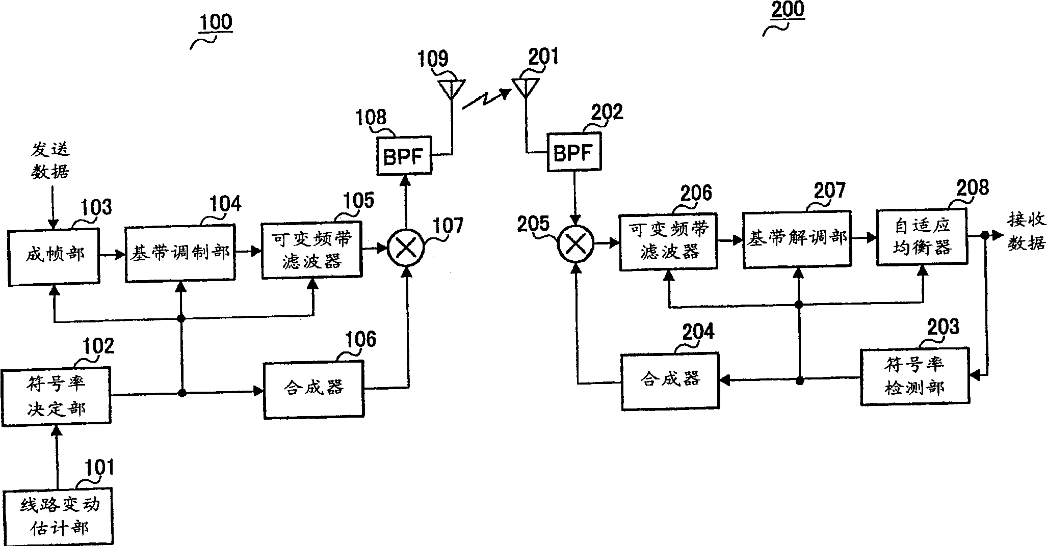
[0020] figure 1 A block diagram showing the structures of the transmitting device and the receiving device according to Embodiment 1 of the present invention.
[0021] exist figure 1 In the transmission device 100 shown, the channel fluctuation estimation unit 101 estimates the channel fluctuation amount between the transmission device 100 and the reception device 200 , and outputs the estimation result to the symbol rate determination unit 102 . As a method of estimating channel fluctuations, there is a method of measuring the reception level of a signal received by a receiving device (not shown) mounted on a base station device or the like together with the transmitting device 100, and based on the measurement result. estimate.
[0022] The symbol rate determination unit 102 determines the symbol rate based on the estimated channel variation. Then, the symbol rate determination unit 102 outputs a signal indicating the determined symbol rate to the framing unit 103 , the b...
Embodiment 2
[0041] Figure 4 A block diagram showing the structures of a transmitting device and a receiving device according to Embodiment 2 of the present invention. Among them, in Figure 4 In the sending device and receiving device shown, pair with figure 1 The same structural part is appended with figure 1 The same reference numerals are used, and descriptions thereof are omitted.
[0042] exist Figure 4 in, compared to figure 1 Specifically, the transmission device 100 adopts a configuration in which the channel fluctuation estimation unit 101 and the symbol rate determination unit 102 are removed, and the demodulation unit 401 and the symbol rate extraction unit 402 are added. Additionally, compared to figure 1 In other words, the reception device 200 adopts a configuration in which the symbol rate detection unit 203 is removed, and the channel estimation fluctuation estimation unit 301 , the symbol rate determination unit 302 , and the modulation unit 303 are added. exist ...
Embodiment 3
[0048] In Embodiments 1 and 2, the case where the symbol rate determining unit 102 or the symbol rate determining unit 302 determines the symbol rate of the transmission data based only on the amount of channel variation has been described.
[0049] However, even for the same delayed wave, the number of delayed symbols becomes relatively larger after the symbol rate is increased. The number of delayed symbols that can be equalized by the adaptive equalizer is determined by the number of taps of the adaptive equalizer. Therefore, when the symbol rate is continuously increased In some cases, there is a delay wave exceeding the possible range, which causes a problem that the performance of the adaptive equalizer deteriorates.
[0050] For example, a delayed wave of 1 μs existing in a wireless line is delayed by one symbol when the symbol rate is 1 Msps, and is delayed by two symbols when the symbol rate is 2 Msps.
[0051] In the case where the adaptive equalizer is 5 taps, equal...
PUM
 Abstract
Description
Claims
Application Information
 - R&D Engineer
- R&D Manager
- IP Professional
- Industry Leading Data Capabilities
- Powerful AI technology
- Patent DNA Extraction
Browse by: Latest US Patents, China's latest patents, Technical Efficacy Thesaurus, Application Domain, Technology Topic, Popular Technical Reports.
© 2024 PatSnap. All rights reserved.Legal|Privacy policy|Modern Slavery Act Transparency Statement|Sitemap|About US| Contact US: help@patsnap.com