
Impeller for fan, fan using same and air conditioner using the fan

A technology for fan impellers, impellers, applied in components, machines/engines, applications, etc. of pumping devices for elastic fluids, which can solve problems such as limitations

Active Publication Date: 2007-05-30
GREE ELECTRIC APPLIANCES INC +1
View PDF5 Cites 0 Cited by
  • Summary
  • Abstract
  • Description
  • Claims
  • Application Information

AI Technical Summary

Problems solved by technology

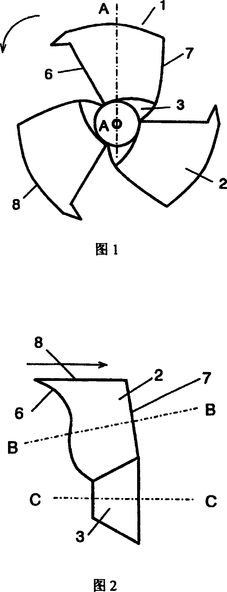
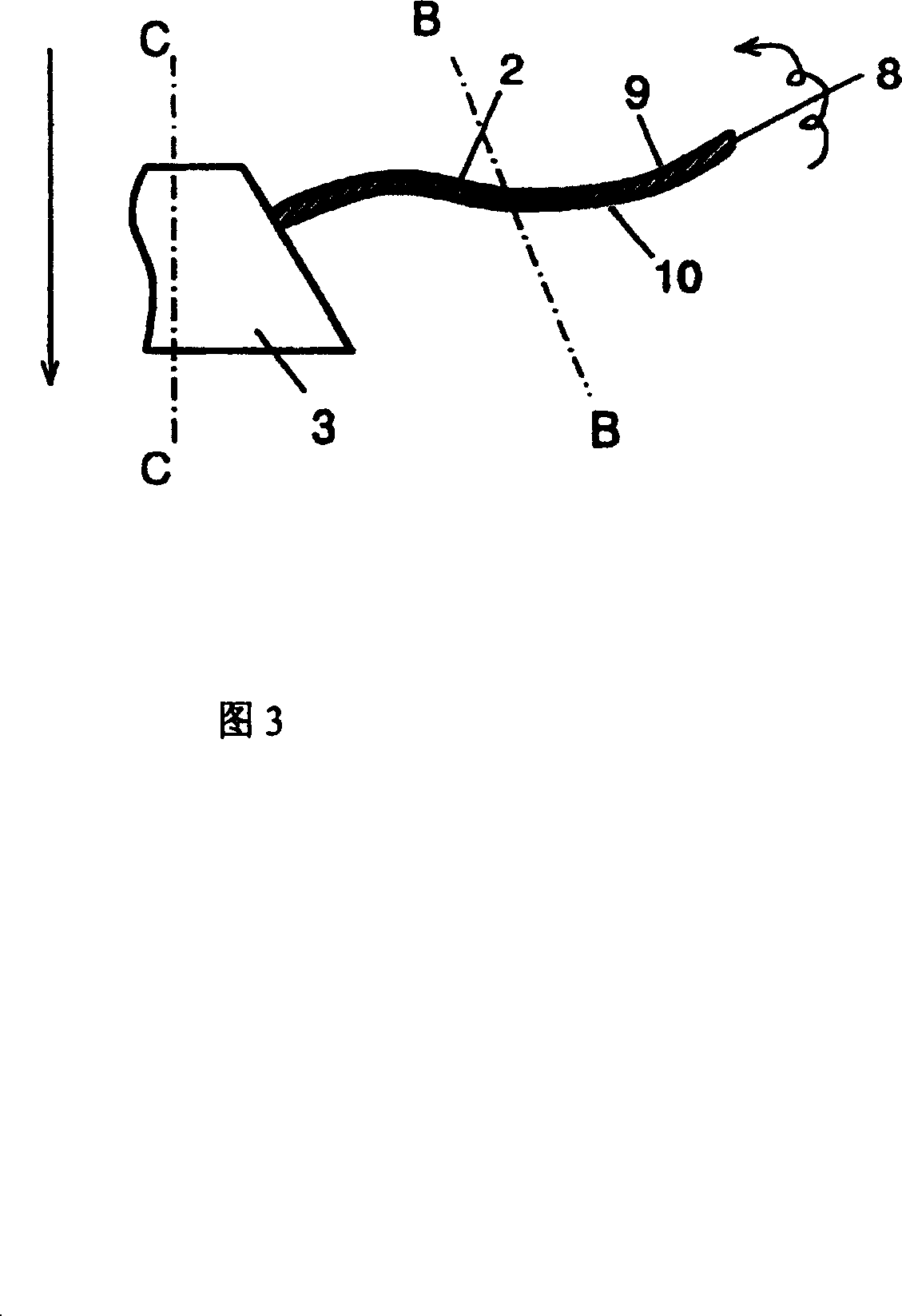
Therefore, when the fan is running, the control of the blade end vortex that occurs near the blade end 8 of the blade 2 and is stripped from the negative pressure surface of the blade near the trailing edge is limited.

Method used


Image

  • Impeller for fan, fan using same and air conditioner using the fan
  • Impeller for fan, fan using same and air conditioner using the fan
  • Impeller for fan, fan using same and air conditioner using the fan

Examples


Embodiment Construction

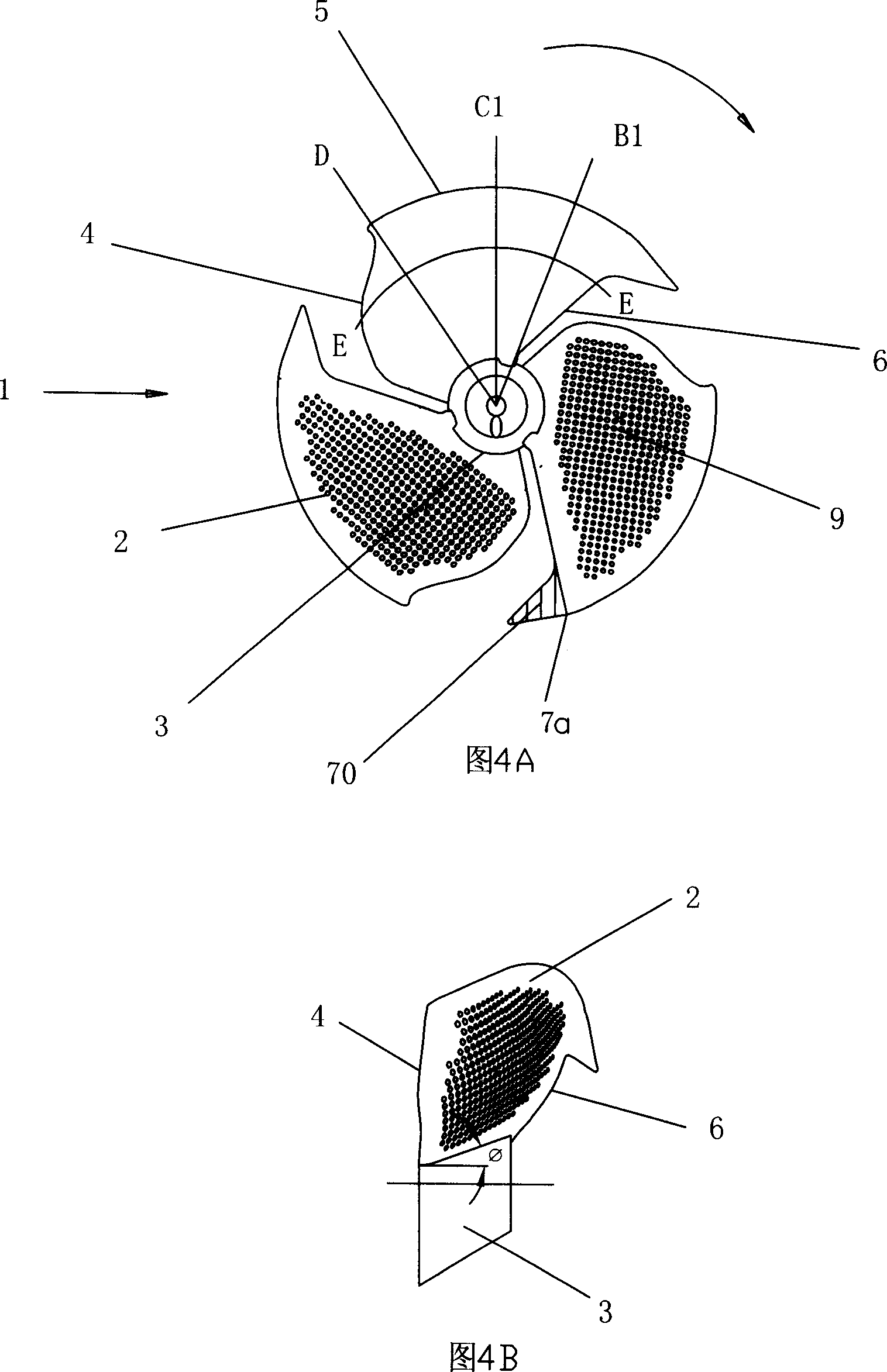
[0020] As shown in Figure 4A, the air conditioner fan impeller 1 is centered on a hub 3 with a substantially truncated conical cross-section, and is provided with three blades 2 radially; the three blades 2 have the same shape, and each blade 2 is evenly distributed. On hub 3. Arrows indicate the direction of rotation of the impeller.

[0021] As shown in Figures 4A and 5A, the shape of the blade 2 is roughly fan-shaped, and the trailing edge 4 of the blade is a convex curve from the root of the hub 3 of the blade to the middle of the blade, and a convex curve from the middle of the blade to the tip 5 of the blade. concave curve. At the part of the leading edge 6 of the blade near the blade end 5, there is a triangular auxiliary blade 70; the end 7a point of the auxiliary blade coincides at the intersection of the blade leading edge 6 and the blade end 5, and the triangular auxiliary blade 70 One side is in close contact with the front edge 6 and integrally arranged. With t...


PUM


Abstract

This invention relates to an impeller wheel used in the fan of air conditioner and especially to the leaf shape of the impeller wheel. The said fan wheel has a hub with multiple leaves and processes the section shape of the leaf radius direction into the leaf topside into the concaved curve and processes the negative pressure side of the hub into convex curve.

Description

technical field [0001] The present invention relates to an impeller used on a fan such as an air conditioner, a fan using the impeller and an air conditioner using the fan, and particularly relates to the blade shape of the impeller. Background technique [0002] The fan impeller of traditional air conditioner is shown in Figure 1, and the blade 2 that is made up of is arranged radially around the wheel hub 3 that is slightly truncated cone shape, and the arrow indicates the direction of rotation; most of the air flow flows into the leading edge 6 of blade 2, And out from the trailing edge 7, the impeller 1 blows air in such a way. FIG. 2 is a partial view of the blade 2 rotation track surface of the impeller 1 . In FIG. 2 , the rotating surface delineated by the leading edge 6 of the blade 2 is concave and convex in the upper half and the lower half respectively relative to the windward surface. The upper half of the blade 2 is defined as surrounding the part between the ...

Claims


Application Information

Patent Timeline
Patent Type & Authority Patents(China)
IPC IPC(8): F04D29/38F04D29/30F04D29/66F24F7/06
Inventor 黄辉金海元袁国强
Owner GREE ELECTRIC APPLIANCES INC
Learn More