Centrifugal fan and air fluid machinery using the same

A centrifugal fan and air technology, which is applied to the parts of the elastic fluid pumping device, mechanical equipment, liquid fuel engine, etc., can solve the problem of loud noise, reduce the efficiency of air supply, and the shape of the blade inlet cannot follow the suction flow, etc. problem, to achieve the effect of high efficiency and low noise efficiency

Inactive Publication Date: 2012-06-27
HITACHI IND EQUIP SYST CO LTD
View PDF10 Cites 0 Cited by
  • Summary
  • Abstract
  • Description
  • Claims
  • Application Information

AI Technical Summary

Problems solved by technology

However, when the designed air volume is different from the actual operating state, the inlet shape of the blade cannot follow the suction flow
Therefore, a large-scale peeling vortex is generated from the blade leading edge 3a, the area of ​​the blade inlet is reduced, and the peeling phenomenon on the side of the negative pressure surface of the blade 3 becomes larger, resulting in loud noise, and further, there is a possibility of reducing the air blowing efficiency.

Method used


Image

  • Centrifugal fan and air fluid machinery using the same
  • Centrifugal fan and air fluid machinery using the same
  • Centrifugal fan and air fluid machinery using the same

Examples


Embodiment Construction

[0053] Hereinafter, embodiments of the present invention will be described in detail with reference to the drawings.

[0054] First, with regard to the centrifugal fan which is the first embodiment of the present invention and the fan filter unit which is an example of an air fluid machine using it, an attached figure 1 ~ attached Figure 5 Explain in detail.

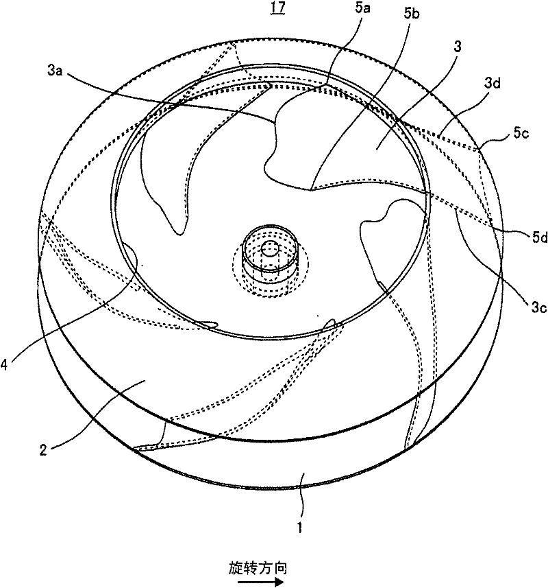
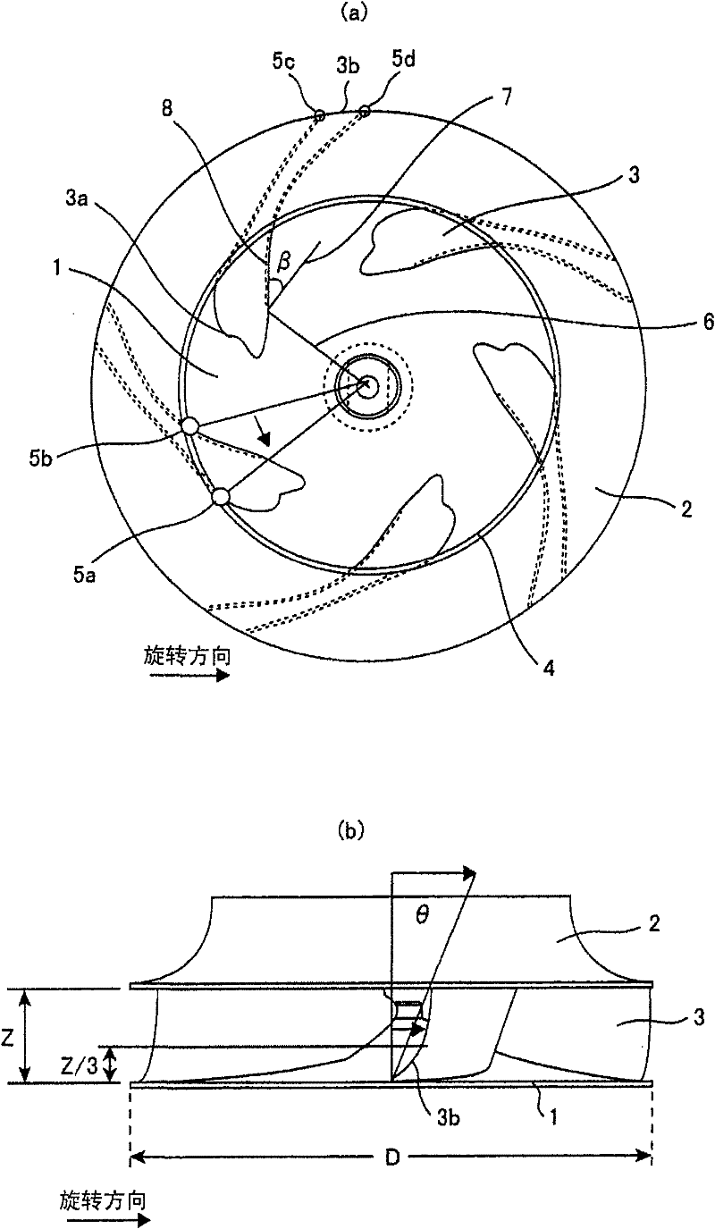
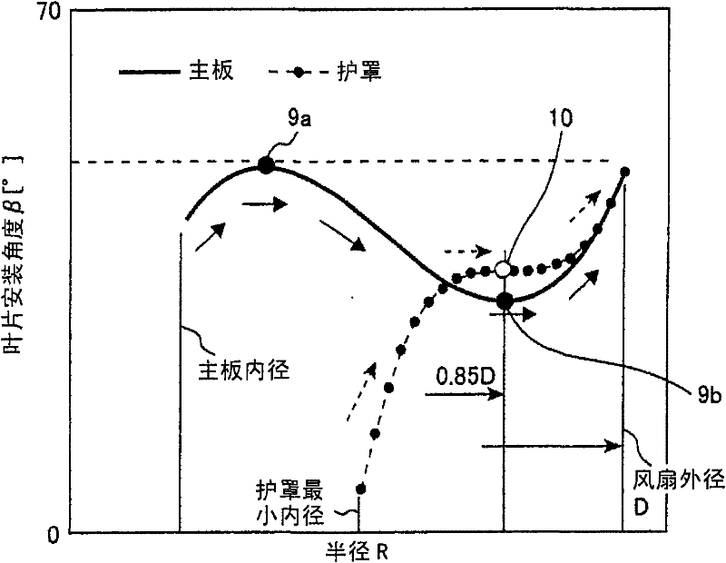
[0055] figure 1 It is a perspective view showing a centrifugal fan 17 provided with blades according to the present invention, figure 2 (a) represents its front view, and, figure 2 (b) shows its side view. and, image 3 Indicates the contact surface between the blade 3 and the shroud constituting the centrifugal fan 17 according to the present invention (refer to Figure 4 3d) and the contact surface with the motherboard (refer to Figure 4 3c) Diagram of the blade installation angle. further, Figure 4 yes figure 1 A side view of the blade 3 of the centrifugal fan 17, and, attached Figure 5 A cross-se...


PUM


Abstract

The present invention provides a centrifugal fan and an air fluid machinery which can inhibit stripping phenomenon of inner part of the fan within a large operating range and meet low noise and high effect of the operating air flow within a large range. In the centrifugal fan, a blade is arranged along the circumferential direction between a ring-shaped shield for forming a suction inlet and a mainboard arranged opposite to the shield, the blade along the radial direction boosts pressure and sprays out the fluid attracted from the axial direction, the shape of the front edge of the blade has a concave-shaped body at the approximately central position in the height direction and has convex-shaped bodies at the mainboard and the shield sides, in the front edge of the blade of an suction inlet, the front edge of the shield side goes forward along the rotation direction compared with the front edge of the mainboard, the mounting angle of the mainboard of the blade has two inflection points with the trend outer diameter, and the mounting angle of the shield is formed by one inflection point, thereby can realize high efficiency and low noise of the centrifugal fan at the design point and the low wind area.

Description

technical field [0001] The present invention relates to a centrifugal fan and an air fluid machine such as an air blower equipped with the centrifugal fan for discharging and supplying air. The structure of the noise generated by centrifugal fans. Background technique [0002] Existing centrifugal fans, for example, are also shown in the following patent document 1, usually as attached Figure 11 and attached Figure 12 As shown, the existing centrifugal fan includes: a main board 1, which is connected with the motor rotating shaft; an annular shroud 2, which is arranged on the relative position of the main board 1; and a plurality of blades 3, which are spaced apart in the circumferential direction. It is arranged between the main board 1 and the shroud 2, and the leading edge 3a of the blade is located on the inner diameter compared with the suction diameter of the shroud, and on the other hand, the trailing edge 3b is located on the outer peripheral edge of the main boar...

Claims


Application Information

Patent Timeline
Patent Type & Authority Patents(China)
IPC IPC(8): F04D17/08F04D29/30
CPCF04D29/30F04D29/281F05D2240/303
Inventor 本多武史佐藤博利杉村和之
Owner HITACHI IND EQUIP SYST CO LTD
Why Eureka
Try Eureka