


Quick Research
Generate reliable direction feasibility study reports for your R&D in just a few steps.

Technical Q&A
Discover and master advanced knowledge NOW. Basics, ideas, possibilities, all at once.

Find Solutions
As an expert in R&D theories, this can generate solutions to your technical problems instantly.

Evaluate Feasibility
Analyze your overall solution with one click, know your potential R&D risks in advance.

Monitor Landscape
Get weekly tech updates, stay abreast of the latest tech innovations and key insights.
Fuel jetter of engine
A technology of fuel injection device and engine, which is applied in the directions of fuel injection device, low pressure fuel injection, low pressure fuel injection, etc., to achieve the effect of avoiding processing procedures and the number of parts, and easy disposal of volatile gas
- Summary
- Abstract
- Description
- Claims
- Application Information
AI Technical Summary
Problems solved by technology
Method used
Image

Examples
Embodiment Construction
[0022] Hereinafter, an embodiment of the present invention will be described based on an example of the present invention shown in the drawings.
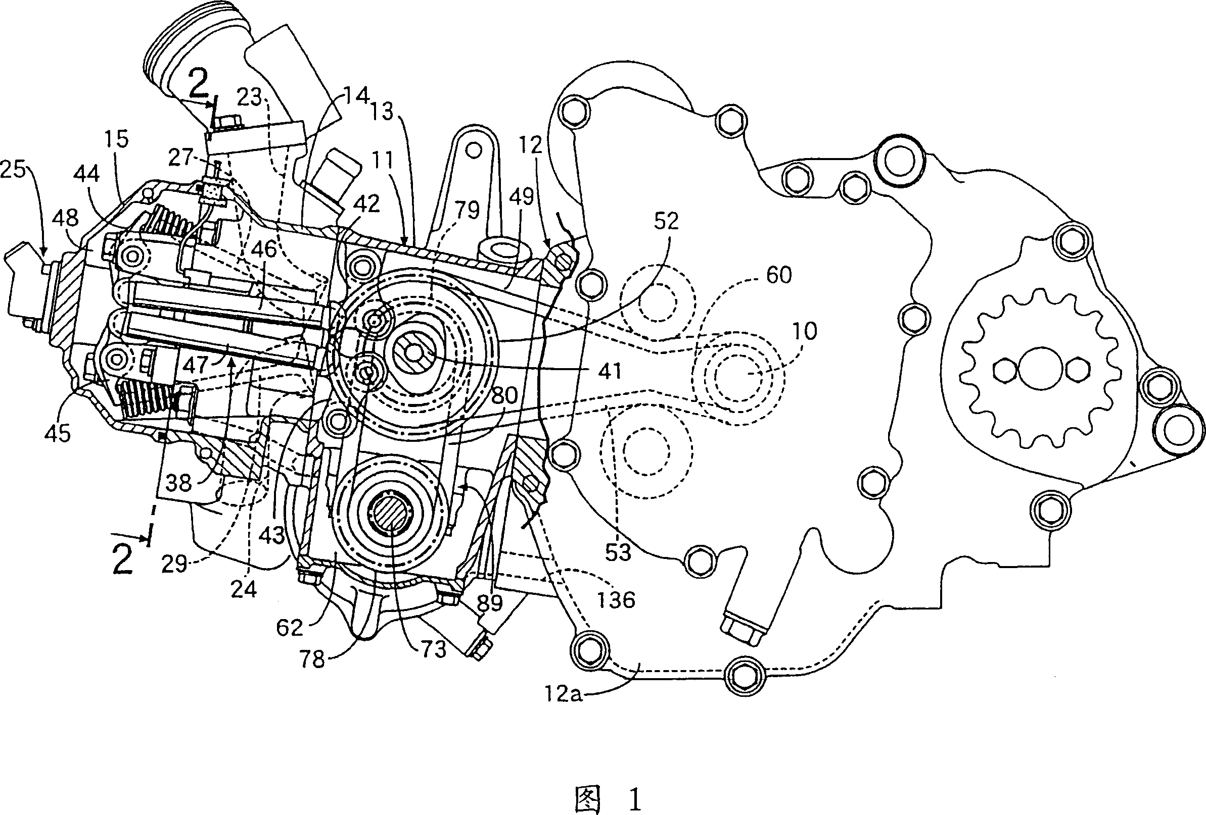
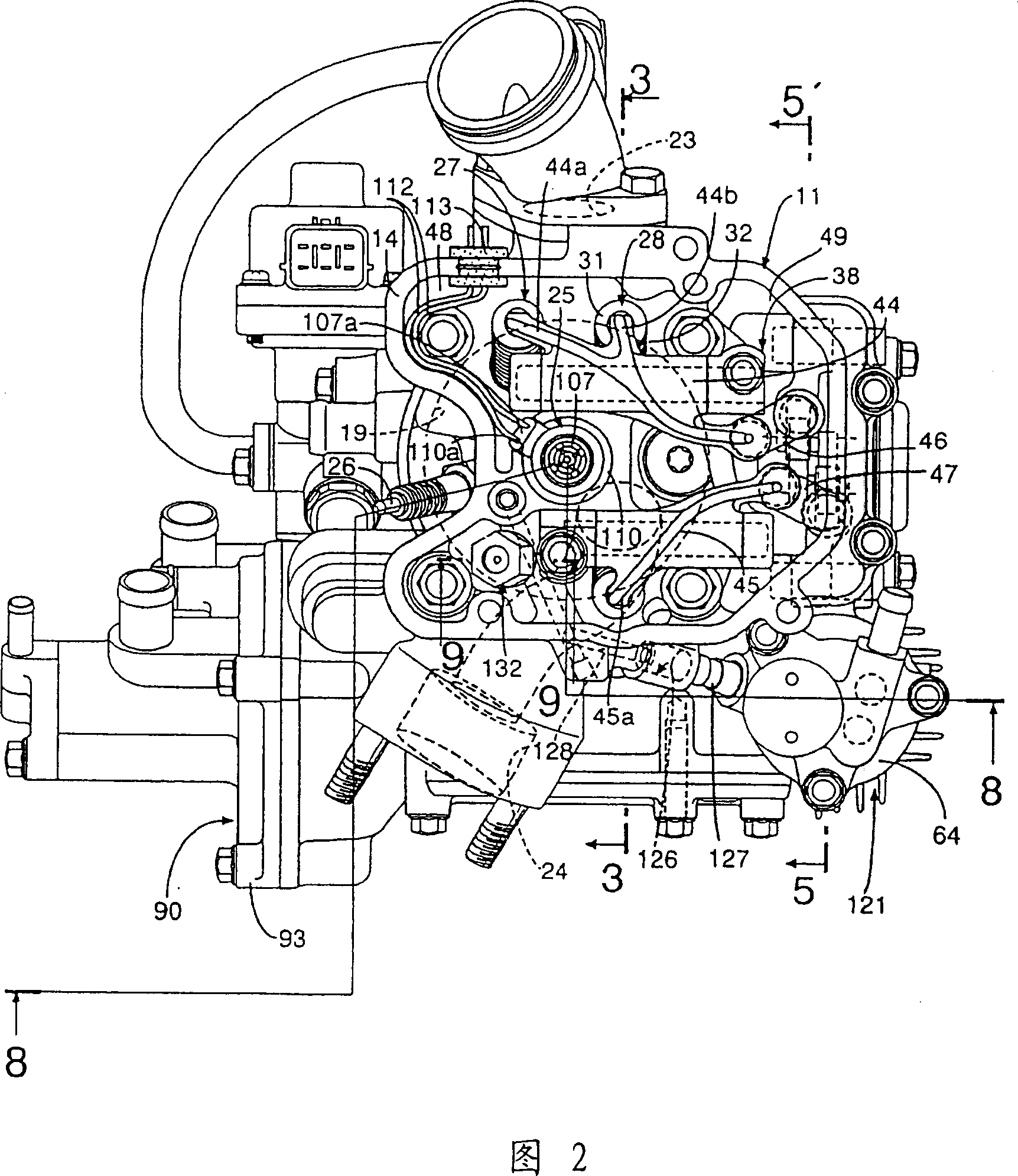
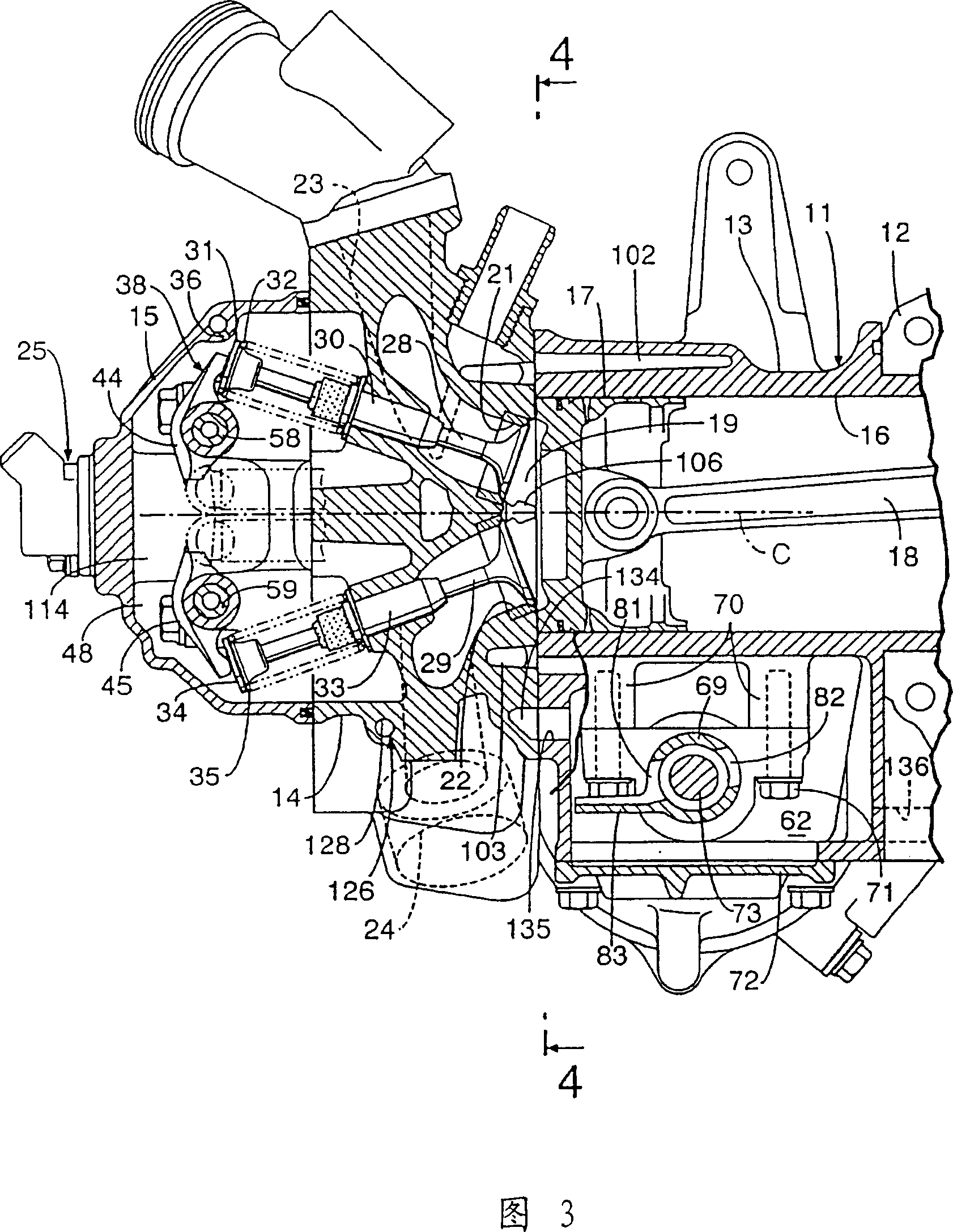
[0023] Figures 1 to 9 show an embodiment of the present invention, Figure 1 is a partial longitudinal sectional side view of the engine, Figure 2 is a view along line 2-2 of Figure 1 when the cover is removed, and Figure 3 is a view of the line of Figure 2 3-3 line sectional view, Fig. 4 is a 4-4 line sectional view of Fig. 3, Fig. 5 is a 5-5 line sectional view of Fig. 2, Fig. 6 is a 6-6 line sectional view of Fig. 5, and Fig. 7 is a 7- 7 line sectional view, FIG. 8 is a longitudinal sectional side view of the engine along line 8-8 in FIG. 2 , and FIG. 9 is an enlarged sectional view along line 9-9 in FIG. 2 .
[0024] Referring first to Fig. 1, the engine body 11 of the overhead valve type four-stroke water-cooled single-cylinder engine comprises: a crankcase 12, a cylinder block 13 combined with the crankcase 12, and the cylinder...
PUM
 Abstract
Description
Claims
Application Information
 - R&D Engineer
- R&D Manager
- IP Professional
- Industry Leading Data Capabilities
- Powerful AI technology
- Patent DNA Extraction
Browse by: Latest US Patents, China's latest patents, Technical Efficacy Thesaurus, Application Domain, Technology Topic, Popular Technical Reports.
© 2024 PatSnap. All rights reserved.Legal|Privacy policy|Modern Slavery Act Transparency Statement|Sitemap|About US| Contact US: help@patsnap.com