Radiating fan structure

A heat dissipation fan and heat sink technology, applied in the field of heat dissipation fans, can solve the problems of air flow loss, difficult heat dissipation efficiency, and the inability of cooling air flow to flow into the heat sink 20 smoothly, so as to slow down the rapid loss, prolong the time of heat exchange, and improve the overall The effect of cooling efficiency

Inactive Publication Date: 2007-04-11
INVENTOR PRECISION
View PDF6 Cites 0 Cited by
  • Summary
  • Abstract
  • Description
  • Claims
  • Application Information

AI Technical Summary

Problems solved by technology

Although the cooling fan has an integrally formed fan housing 10 and heat sink 20, which makes it simple in structure and suitable for ultra-thin and small electronic devices, the airflow is easy to flow directly from the equal-width airflow channel 22a between the two fins. Therefore, sufficient heat exchange cannot be performed, and it is difficult to further improve the overall heat dissipation efficiency
Furthermore, the inner wall of the side wall 11 of the fan housing 10 forms a corner 14 on the two sides of the air outlet 13 respectively, so that the cooling air cannot flow into the heat sink 20 smoothly, thus affecting the overall heat dissipation efficiency.

Method used


Image

  • Radiating fan structure
  • Radiating fan structure
  • Radiating fan structure

Examples


Embodiment Construction

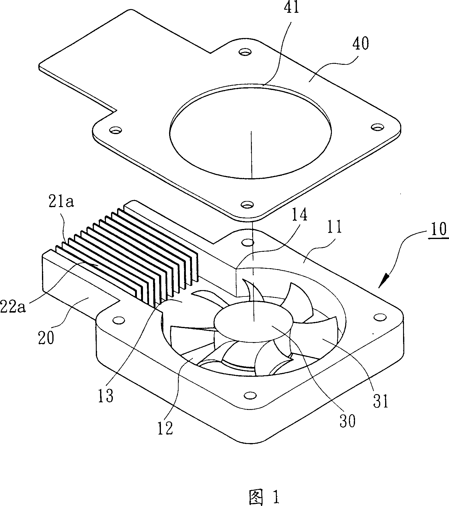
[0018] Part of the structure of the heat dissipation fan in the present invention is the same as that of the traditional heat dissipation fan shown in Figure 1, and the parts with the same structure are shown with the same label, for this reason, in the following embodiments, for the parts with the same label The specific structure and function will not be described in detail again.

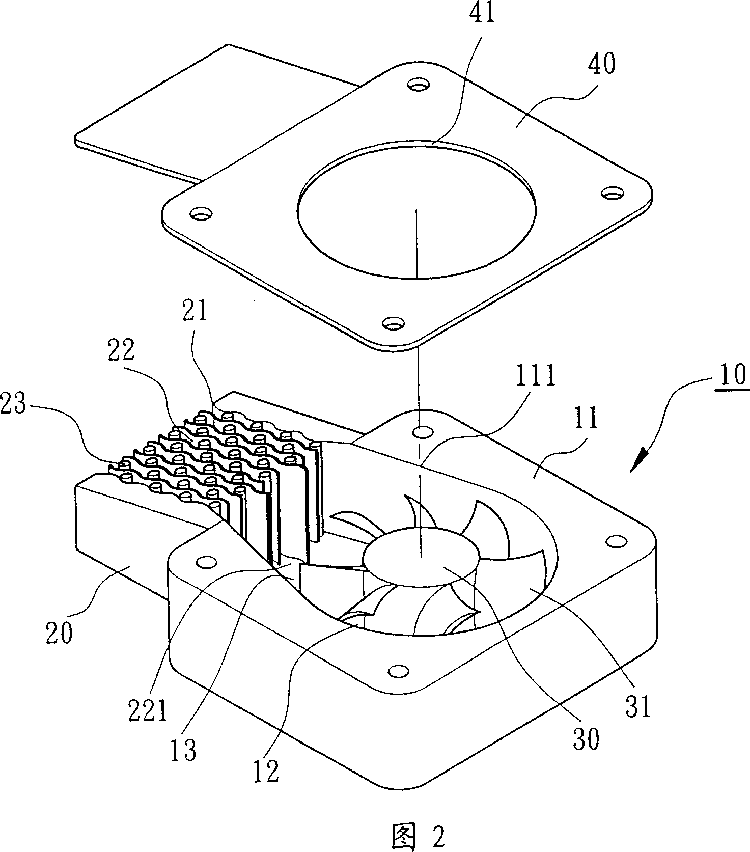
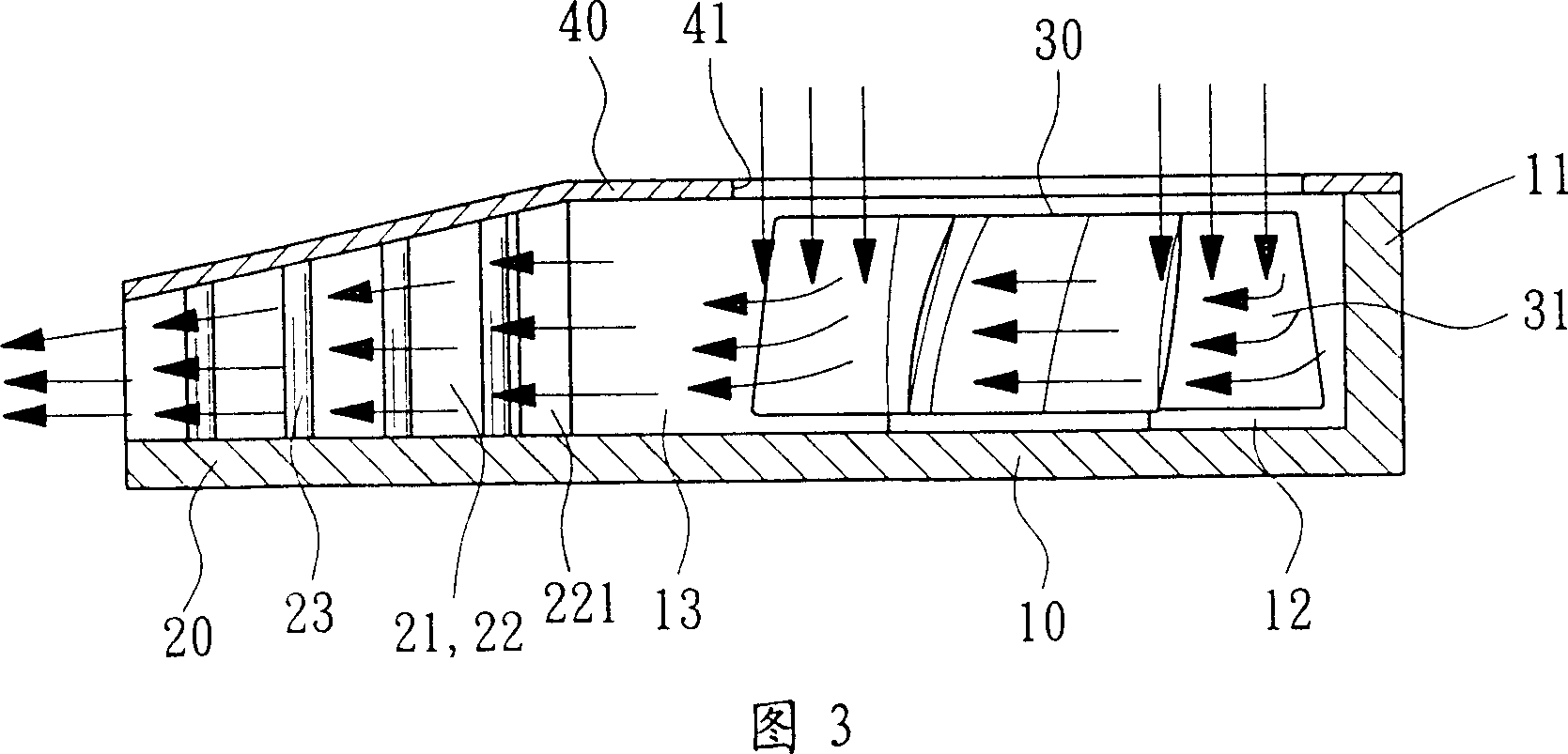
[0019] As shown in FIGS. 2 and 3 , the cooling fan structure in the first embodiment of the present invention includes a fan casing 10 , a cooling fin 20 , a fan wheel 30 and an upper cover 40 . The fan housing 10 is provided with several side walls 11, a chamber 12 and at least one air outlet 13; the cooling fin 20 is arranged outside the air outlet 13 of the fan housing 10; the fan wheel 30 is located in the chamber 12, and has several a blade 31 ; the upper cover 40 is set on the top of the fan housing 10 and the heat sink 20 , and is provided with an air inlet 41 .

[0020] As shown in Figur...


PUM


Abstract

A radiating fan structure includes a casing, a set of radiating ribs, a fan wheel, and a cover. The radiating ribs are located at the outlet of the fan, having several channels and posts. The sectional area of inlet is larger than that of outlet so as to form a booster structure to prolong heat exchange time between air and radiating ribs.

Description

technical field [0001] The present invention relates to a heat dissipation fan, and more specifically relates to a heat dissipation fan that is arranged outside the air outlet of the fan casing, uses the heat dissipation fins to form several airflow channels, and further forms a pressurized slow flow structure to improve the overall heat dissipation. Efficient cooling fan structure. Background technique [0002] The traditional cooling fan structure, as shown in FIG. 1 , includes a fan casing 10 , a cooling fin 20 , a fan wheel 30 and an upper cover 40 . The fan casing 10 is formed by a plurality of sidewalls 11 to form a chamber 12 and at least one air outlet 13 . The cooling fins 20 are integrally formed on the outside of the air outlet 13 , and are protrudingly provided with several fins 21a forming several cooling channels 22a. The fan wheel 30 is set in the chamber 12 and has several blades 31 . The upper cover 40 is disposed above the fan casing 10 and the heat sink...

Claims


Application Information

Patent Timeline
IPC IPC(8): F04D29/44F04D29/58H01L23/367H01L23/467F28F3/02F04D29/54
Inventor 陈建裕
Owner INVENTOR PRECISION
Why Eureka
Try Eureka