
Steel band side treating process

A processing technology and edge technology, which is applied in the field of large-scale cold-formed steel production line technology to achieve the effect of reducing investment costs

Inactive Publication Date: 2007-04-04
BAOSTEEL GRP NANTONG WIRE PROD
View PDF5 Cites 0 Cited by
  • Summary
  • Abstract
  • Description
  • Claims
  • Application Information

AI Technical Summary

Problems solved by technology

[0003] The purpose of the present invention is to solve the above problems, propose a kind of not using edge milling machine, adopt the combination of edge disc cutter and edge planer, supplemented by edge extrusion molding process in the forming process, solve the problem of high frequency Steel Strip Edge Treatment Process for Parallelism of Steel Ends to be Welded

Method used


Image

  • Steel band side treating process
  • Steel band side treating process
  • Steel band side treating process

Examples


Embodiment Construction

[0016] Below, with reference to the accompanying drawings, the embodiment of the steel strip edge processing technology and the device used in the present invention will be described in detail.

[0017] The steel strip edge processing technology and the device used in the present invention are combined with edge disc shears and edge planer, supplemented by edge extrusion molding in the forming process, which solves the problem of high-frequency parallelism of the steel ends to be welded. Degree problem.

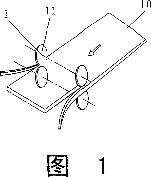
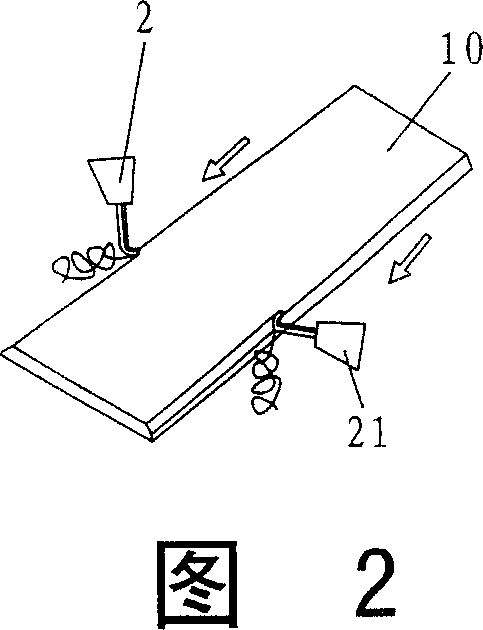
[0018] The disc shears in the present invention first cut the edge of the raw material to determine the width, and then the edge is planed out of the groove by the edge planer. Measure the edge bevel to the final welding process angle and end surface quality.

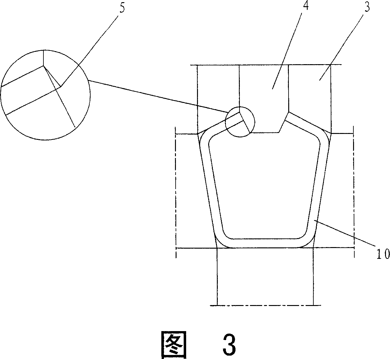
[0019] Referring to Fig. 1 Fig. 2, Fig. 3, wherein, Fig. 1 is the schematic diagram that utilizes disc shearing edge trimming process in the present invention; Fig. 2 is the schematic diagram that utilizes edge planer...


PUM


Abstract

The invention is a steel belt edge processing technique, combining edge disc shears and edge digger and assorted with edge extrusion molding to resolve the parallelism problem of HF steel end to be welded. It firstly uses the disc shears to shear the edges and determine the width, then uses the edge digger to dig sloping mouth, when the raw material enters the closed fin pass frame of the main machine, applying a certain rolling quantity to make the sloping mouth reach the final welding technical angle and end surface quality. It reduces capitalized cost of the whole large cold bending shape steel production line.

Description

(1) Technical field [0001] The invention relates to a large-scale cold-formed steel production line process, in particular to a steel strip edge treatment process in the large-scale cold-formed steel production line. (2) Background technology [0002] During the forming process of large-scale thick-walled cold-formed steel products, the end of the steel to be welded entering the high-frequency welding area has a certain angle due to bending, which affects the quality of high-frequency welding. The existing method is to configure an edge milling machine in front of the main machine to mill the end of the raw material to be welded into a certain chamfer, so as to achieve the parallelism of the steel end to be welded entering the high-frequency welding zone. However, the currently used edge milling machines can only be imported, which is expensive, and the cost of use and maintenance is relatively high. (3) Contents of the invention [0003] The purpose of the present invent...

Claims


Application Information

Patent Timeline
Patent Type & Authority Patents(China)
IPC IPC(8): B23P23/04
Inventor 郁竑钱伟中唐宇翚马越峰
Owner BAOSTEEL GRP NANTONG WIRE PROD
Learn More