Short edge cutting broaching fine broach and short edge cutting combined broaching fine broaching
A technology of fine broaching and cutting edge, applied in the field of short-edge cutting broaching fine broaching and short-edge cutting combined broaching fine broaching, can solve the problems of cylinder slide groove parallelism and poor surface roughness, etc. The effect of increased tool life, increased machining difficulty, and improved life
- Summary
- Abstract
- Description
- Claims
- Application Information
AI Technical Summary
Problems solved by technology
Method used
Image
Examples
Embodiment 1
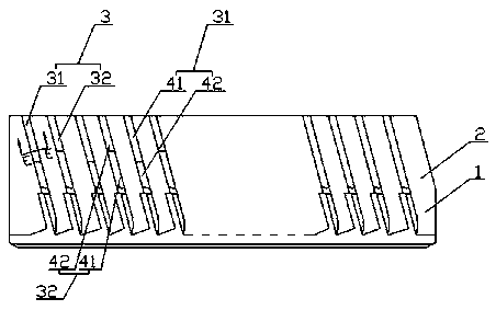
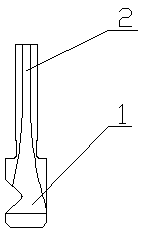
[0031] Such as figure 1 , 2 As shown in , 5, the short-edge cutting broaching finishing broach includes a support part 1, a broach part 2 is arranged on the support part 1, and a cutting tooth 3 is arranged on the broach part 2, and the cutting tooth 3 is pressed according to the workpiece to be processed. The contact sequence consists of odd-numbered cutting teeth 31 and even-numbered cutting teeth 32; wherein both odd-numbered cutting teeth 31 and even-numbered cutting teeth 32 are composed of interconnected cutting edge portions 41 and non-cutting edge portions 42, wherein the cutting edges on odd-numbered cutting teeth 31 The cutting edge portion 41 and the cutting edge portion 41 on the even-numbered cutting teeth 32 are staggered from each other.
[0032] In this embodiment, since most powder metallurgy cylinders are small in size and low in cylinder height, the traditional finishing broach is prone to the phenomenon that the parallelism is out of tolerance when machini...
Embodiment 2
[0034] Such as figure 1 , 2 , 5, compared with embodiment 1, the present embodiment optimizes the broach part 2, the broach part 2 is sheet-shaped, and the cutting teeth 3 are arranged symmetrically on both sides of the broach part 2; in the broach part On one side of 2: the non-cutting edge portion 42 on the odd-numbered cutting teeth 31 is set close to the support portion 1, and the cutting edge portion 41 on the even-numbered cutting teeth 32 is set close to the support portion 1.
Embodiment 3
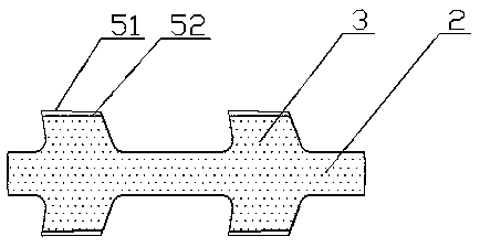
[0036] Such as image 3 As shown, compared with Embodiment 2, this embodiment optimizes the cutting edge portion 41 and the non-cutting edge portion 42, and the edge between the cutting edge 51 on the cutting edge portion 41 and the non-cutting edge 52 on the non-cutting edge portion 42. The difference in width and height is 0.02-0.05mm; in this way, the broach will not appear to let the knife and resonate in the process of broaching, and this cutting edge cutting form is conducive to chip breaking of iron chips and avoids sticking of the cutting edge. chipping phenomenon.
PUM
 Abstract
Description
Claims
Application Information
 - Generate Ideas
- Intellectual Property
- Life Sciences
- Materials
- Tech Scout
- Unparalleled Data Quality
- Higher Quality Content
- 60% Fewer Hallucinations
Browse by: Latest US Patents, China's latest patents, Technical Efficacy Thesaurus, Application Domain, Technology Topic, Popular Technical Reports.
© 2025 PatSnap. All rights reserved.Legal|Privacy policy|Modern Slavery Act Transparency Statement|Sitemap|About US| Contact US: help@patsnap.com


