
Time base comprising integrated micromechanical tuning fork resonator

A resonator and micromechanical technology, applied in the field of integrated electronic circuit devices, to achieve high quality factor Q, promote mass production, and low power consumption

Inactive Publication Date: 2006-12-27
ETA SA MFG HORLOGERE SUISSE
View PDF5 Cites 0 Cited by
  • Summary
  • Abstract
  • Description
  • Claims
  • Application Information

AI Technical Summary

Problems solved by technology

Also, assembling and connecting the two components entails additional costs

Method used


Image

  • Time base comprising integrated micromechanical tuning fork resonator
  • Time base comprising integrated micromechanical tuning fork resonator
  • Time base comprising integrated micromechanical tuning fork resonator

Examples


Embodiment Construction

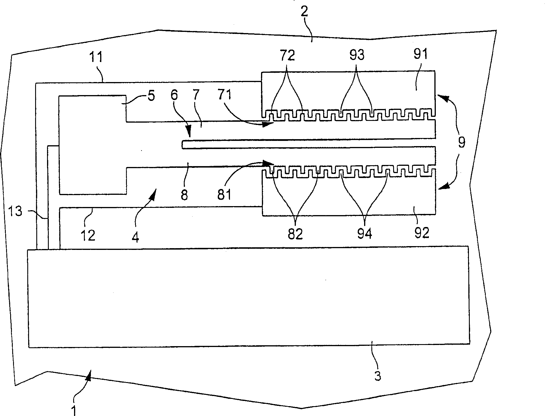
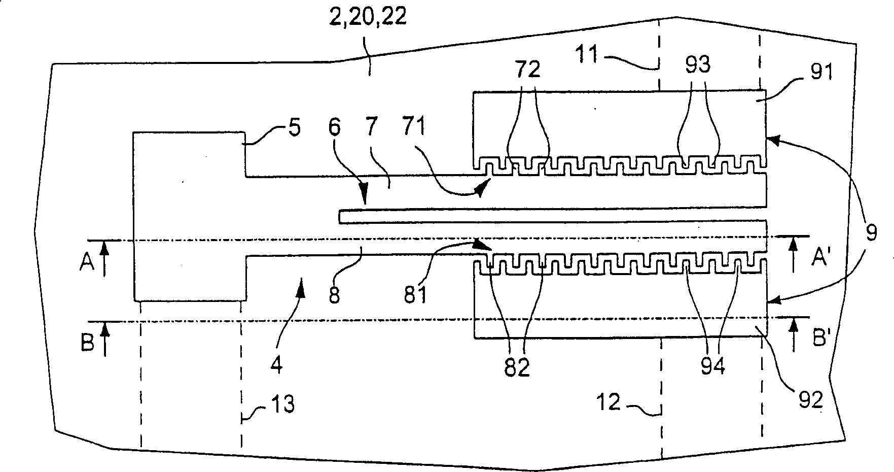
[0042] figure 1 A top view of a time base according to the invention is schematically shown. There is shown an integrated time base, indicated generally at 1, comprising a resonator 4 and an integrated electronic circuit 3 for driving the resonator to oscillate and generating a signal of a predetermined frequency in response thereto. Since the integrated electronic circuit 3 can be easily designed by a person skilled in the art, this circuit is not shown in detail. The integrated electronic circuit 3 and the resonator 4 are preferably realized and integrated on the same substrate, generally indicated by reference numeral 2, such as figure 1 shown. The preferred substrate material is silicon, however other similar materials known to those skilled in the art are also suitable for implementing the time base of the present invention.

[0043] According to the invention, the resonator 4 is realized in the form of a monolithic micromechanical tuning fork resonator. The resonator...


PUM


Abstract

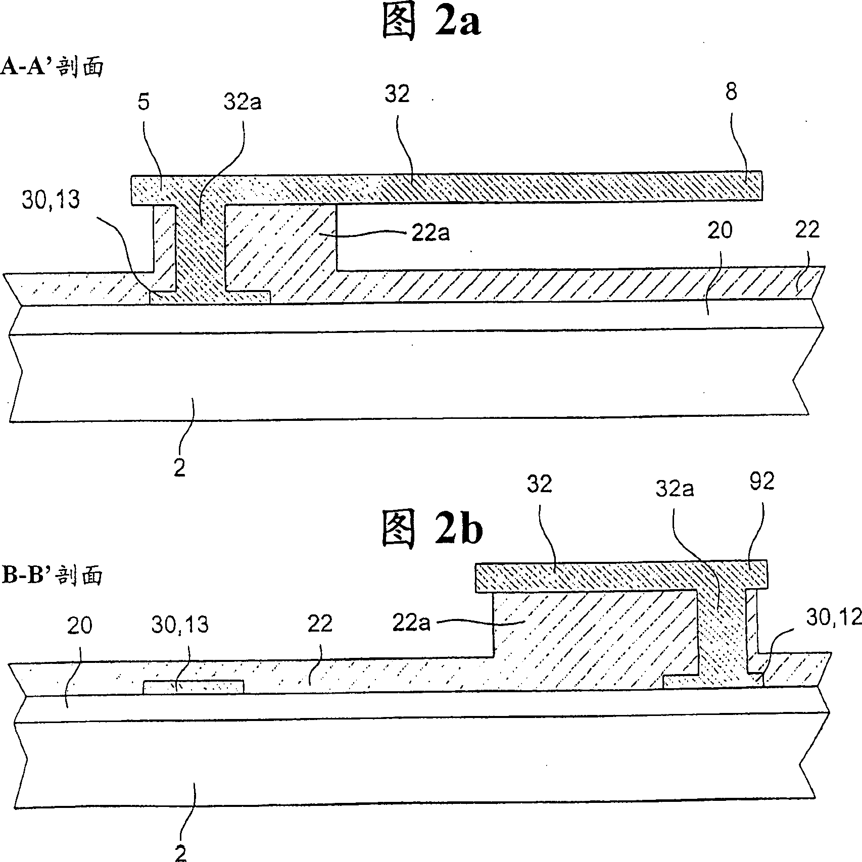
There is described a time base comprising a resonator (4) and an integrated electronic circuit (3) for driving the resonator into oscillation and for producing, in response to this oscillation, a signal having a determined frequency. The resonator is an integrated micromechanical tuning fork resonator (4) supported above a substrate (2) and adapted to oscillate in a plane substantially parallel to the substrate. The tuning fork resonator comprises a base member (5) extending substantially perpendicularly from the substrate, a free-substantially parallel fork tines (7, 8) and an electrode structure (9) disposed adjacent to the fork tines and connected to the integrated electronic circuit.

Description

technical field [0001] The invention relates to a time base, ie a device comprising a resonator and an integrated electronic circuit for driving the resonator to oscillate and generating a signal of a predetermined frequency in response to the oscillation. Background technique [0002] Time base or frequency standards are required in a variety of electronic devices ranging from watches and other timekeeping devices to complex telecommunications devices. Such a time base is usually formed from an oscillator comprising a quartz resonator and an electronic circuit for driving the resonator to oscillate. Additional dividing circuits can be used to divide the signal generated by the oscillator to obtain lower frequencies. Other parts of the circuit can be used to adjust the frequency, for example by adjusting the frequency division ratio of the frequency division circuit. The components of the electronic circuit are preferably integrated on a semiconductor substrate by means of...

Claims


Application Information

Patent Timeline
Patent Type & Authority Patents(China)
IPC IPC(8): H03H9/21H03H9/24B81B3/00G10K15/00H03B5/30
CPCH03H9/21H03H9/2484H03H2009/02299H03B1/00
Inventor M·吉欧索夫H·屈克R·普拉茨
Owner ETA SA MFG HORLOGERE SUISSE
Learn More