Patten drawing device

A pattern and control part technology, which is applied in the field of drawing patterns, can solve the problems such as the increase in the size of the light irradiation mechanism, the increase in the cost of the manufacturing device, and the increase in time.

Inactive Publication Date: 2006-12-27
DAINIPPON SCREEN MTG CO LTD
View PDF1 Cites 0 Cited by
  • Summary
  • Abstract
  • Description
  • Claims
  • Application Information

AI Technical Summary

Problems solved by technology

In the proximity exposure method in which the entire mask pattern is transferred to a photosensitive material, light is irradiated by bringing the mask and the substrate close together, so the price of the mask is relatively high in order to cope with the high precision of the pattern and the increase in the size of the substrate. high
In addition, the proximity exposure method and the step exposure method have the disadvantage that they cannot flexibly respond to changes in the pitch and width of the pattern to be drawn.
[0006] In the direct drawing method, the raster method is generally used, and the pattern is expressed as a collection of tiny dots (pixels), and the pattern is drawn in units of dots. However, in order to correspond to the high precision of the pattern , it is necessary to increase the resolution of the drawing device (that is, to reduce the area of ​​1 dot), and the time required to draw the pattern on the large substrate as a whole increases
[0007] As a way to shorten the drawing time, it is considered to increase the number of beams to be scanned and at the same time to increase the number of dots to be drawn. However, with the increase in the number of beams, the size of the light irradiation mechanism increases and the cost of the manufacturing device increases.

Method used


Image

  • Patten drawing device
  • Patten drawing device
  • Patten drawing device

Examples


Embodiment Construction

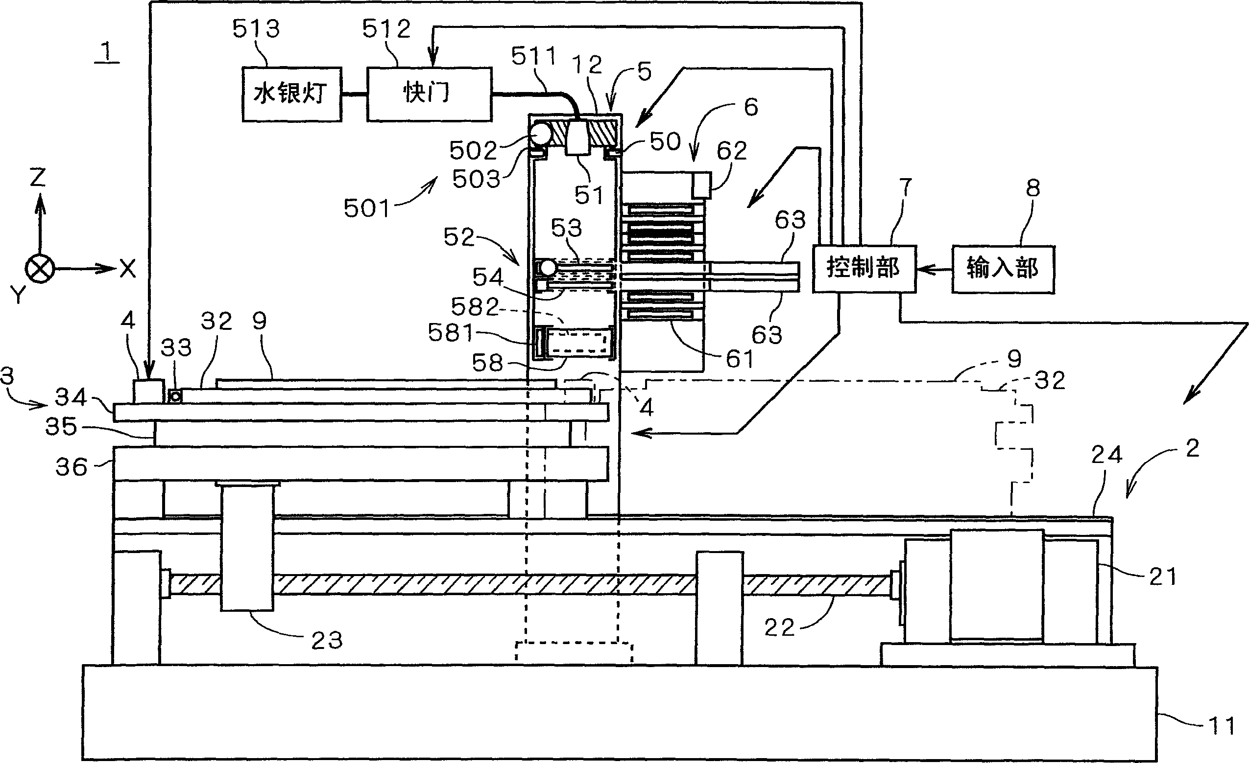
[0027] figure 1 It is a view showing the structure of the pattern drawing device 1 according to the first embodiment of the present invention. The pattern drawing device 1 is such a device that, by irradiating light to a glass substrate 9 (hereinafter simply referred to as "substrate 9") for a liquid crystal display device, the photosensitive material (in this embodiment, "colored") on the substrate 9 A plurality of striped patterns are drawn on the color resist"). The patterned substrate 9 passes through another subsequent process, and finally becomes a color filter as an assembly part of a liquid crystal display device.

[0028] In the pattern drawing apparatus 1, a stage moving mechanism 2 is provided on the base 11, and by this stage moving mechanism 2, the stage assembly 3 holding the substrate 9 can move along the main surface of the substrate 9. figure 1 Move in the X direction. A bracket 12 is fixed to the base 11 so as to straddle the stage assembly 3 , and the hea...


PUM


Abstract

The pattern plotting apparatus 1 is equipped with a stage 32 holding a substrate 9, a stage moving mechanism 2 to move the stage 32, a light emitting part 5 to emit light to the substrate 9, a mask part 52 having a first mask 53 and a second mask 54 formed with a plurality of apertures, and an optical unit 58 to enlarge or reduce the irradiation region on the substrate 9 to be irradiated with the light passing through the mask part 52. In the pattern plotting apparatus 1, the overlapped part of the apertures in the first mask 53 and the second mask 54, and the magnification of the optical unit 58 are varied. Thereby, the width and the pitch of the pattern to be plotted can be easily varied, and a stripe pattern can be plotted at high speed with high resolution on the photosensitive material on the substrate 9.

Description

technical field [0001] The present invention relates to a technique for drawing a pattern by irradiating light to a photosensitive material on a substrate. Background technique [0002] In the past, as a method of drawing a pattern by irradiating light on a photosensitive material formed on a semiconductor substrate, a printed circuit board, or a plasma display device, a liquid crystal display device, a glass substrate for a photomask, etc. (hereinafter referred to as "substrate") As a method, methods for transferring a mask pattern onto a photosensitive material such as a proximity exposure method and a stepper exposure method are known. [0003] In the proximity exposure method, a mask of the same size as the substrate having openings corresponding to the drawn pattern is brought close to the substrate and irradiated with light to transfer the entire pattern onto the photosensitive material on the substrate. In the step exposure method, the projection of the mask pattern ...

Claims


Application Information

Patent Timeline
Patent Type & Authority Patents(China)
IPC IPC(8): G03F7/20G03F7/207G02F1/13H01L21/027H05K3/00
CPCG02F1/1303G03F7/20H01L21/027H05K3/00
Inventor 小八木康幸
Owner DAINIPPON SCREEN MTG CO LTD
Why Eureka
Try Eureka