Direct current power ergometer and its control system

A technology of electric dynamometer and DC motor, applied in power metering, measuring devices, instruments, etc., can solve the problems of waste, impact on measurement accuracy, and more fatal impact on measurement accuracy.

Inactive Publication Date: 2006-11-08
HAIYANG SCI & TECH SHIYAN CITY
View PDF0 Cites 0 Cited by
  • Summary
  • Abstract
  • Description
  • Claims
  • Application Information

AI Technical Summary

Problems solved by technology

[0002] The power measurement equipment used in the traditional power transmission test system is mainly the hydraulic dynamometer and the eddy current dynamometer. Their disadvantage is that the mechanical energy absorbed by the dynamometer is finally converted into heat energy and taken away by the circulating cooling water. The input torque is measured indirectly by measuring the counter torque of the floating casing, and the measurement accuracy will be affected by the friction force of the floating casing bearing and the swing angle of the arm, especially when the floating casing bearing is loaded non-uniformly for a long time After fatigue occurs, the impact on measurement accuracy is more fatal

Method used


Image

  • Direct current power ergometer and its control system
  • Direct current power ergometer and its control system

Examples


Embodiment Construction

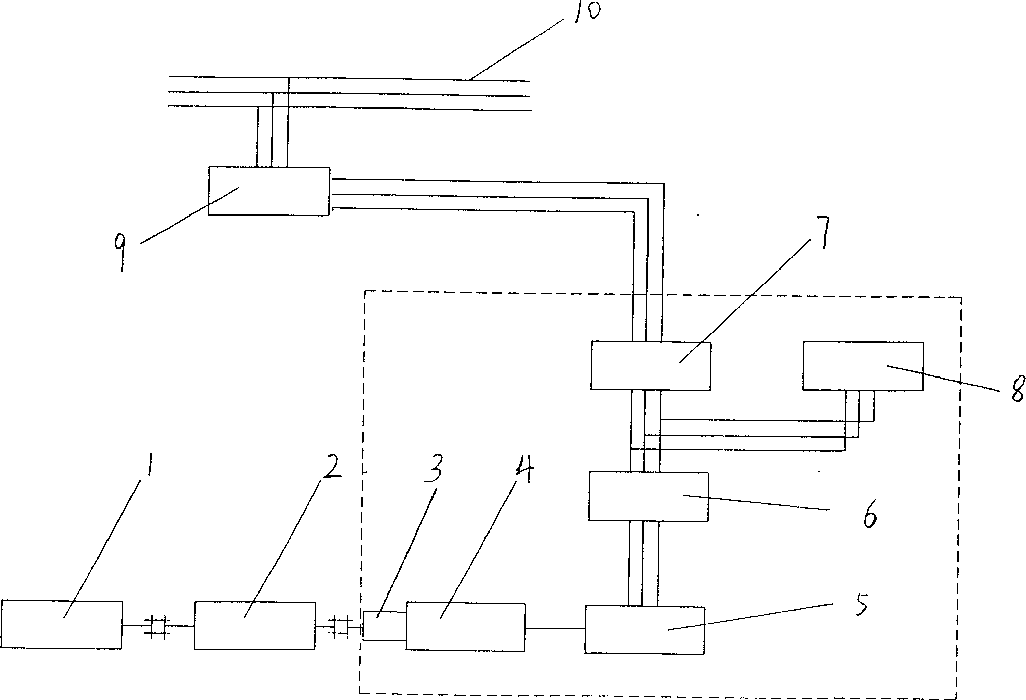
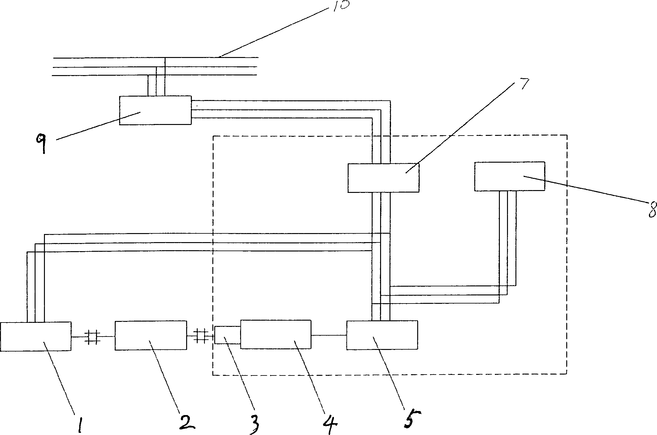
[0005] according to Figure 1 As shown, the mechanical power transmitted by the prime mover 1 through the intermediate device (such as a gearbox) 2 is directly converted into DC power by the dynamometer host 4 (DC motor or DC generator) after being measured by the bearingless torque sensor 3, and then Through the four-quadrant DC motor drive control cabinet 5, it is converted into three-phase AC power that matches the power supply parameters of the power grid in the form of active inversion, and then sent to the output side of the power distribution cabinet 7 after passing through the high-order harmonic isolation transformer 6. The invention also needs to parallel connect the reactive power compensation cabinet at the output side of the power distribution cabinet 7. The three-phase AC power is sent to the power distribution cabinet 7 after the high-order harmonics are eliminated by the isolation transformer 6. Such electric power can be fed back to the grid or sent to the prim...


PUM


Abstract

The purpose of a DC power dynamometer and its control system in the present invention is to convert the mechanical energy absorbed by the dynamometer into DC electric energy, and then convert it into AC electric energy and feed it back to the power grid through an active inverter, and will not be affected by the floating casing. The problem of inaccurate torque measurement due to non-uniform loading of bearings. The invention relates to a DC power dynamometer and its control system, which is characterized in that the input torque of the motor is directly measured by a bearingless torque sensor attached to the input shaft of the dynamometer motor, and the dynamometer motor converts the mechanical energy of the prime mover into DC power Afterwards, it is converted into three-phase AC power that matches the grid power supply parameters through the four-quadrant DC motor drive control cabinet. The invention can fully recover the power transmitted by the system and save energy; the torque measurement is more direct and more accurate.

Description

technical field [0001] The invention relates to an electric dynamometer and its control system, in particular to a DC electric dynamometer and its control system. Background technique [0002] The power measurement equipment used in the traditional power transmission test system is mainly the hydraulic dynamometer and the eddy current dynamometer. Their disadvantage is that the mechanical energy absorbed by the dynamometer is finally converted into heat energy and taken away by the circulating cooling water. The input torque is measured indirectly by measuring the counter torque of the floating casing, and the measurement accuracy will be affected by the friction force of the floating casing bearing and the swing angle of the arm, especially when the floating casing bearing is loaded non-uniformly for a long time After fatigue occurs, the impact on measurement accuracy is even more fatal. Contents of the invention [0003] The purpose of the invention of a DC power dynamo...

Claims


Application Information

Patent Timeline
Patent Type & Authority Patents(China)
IPC IPC(8): G01L3/24
Inventor 李四海
Owner HAIYANG SCI & TECH SHIYAN CITY
Why Eureka
Try Eureka