Two-stroke internal combustion engine

A technology for two-stroke internal combustion engines and scavenging passages, applied to internal combustion piston engines, combustion engines, mechanical equipment, etc., can solve the problems of exhaust gas pollution, entry, and engine operation problems, so as to improve fuel economy and scavenging efficiency , the effect of improving combustion efficiency

Inactive Publication Date: 2006-10-25
KIORITZ
View PDF0 Cites 1 Cited by
  • Summary
  • Abstract
  • Description
  • Claims
  • Application Information

AI Technical Summary

Problems solved by technology

Therefore, the exhaust gas will also be aggravated by the oil components in the fuel.
In addition, depending on the working attitude (inclination) of the engine, the oil components in the fuel will enter the combustion chamber excessively, causing problems in the operation of the engine

Method used


Image

  • Two-stroke internal combustion engine
  • Two-stroke internal combustion engine
  • Two-stroke internal combustion engine

Examples


Embodiment Construction

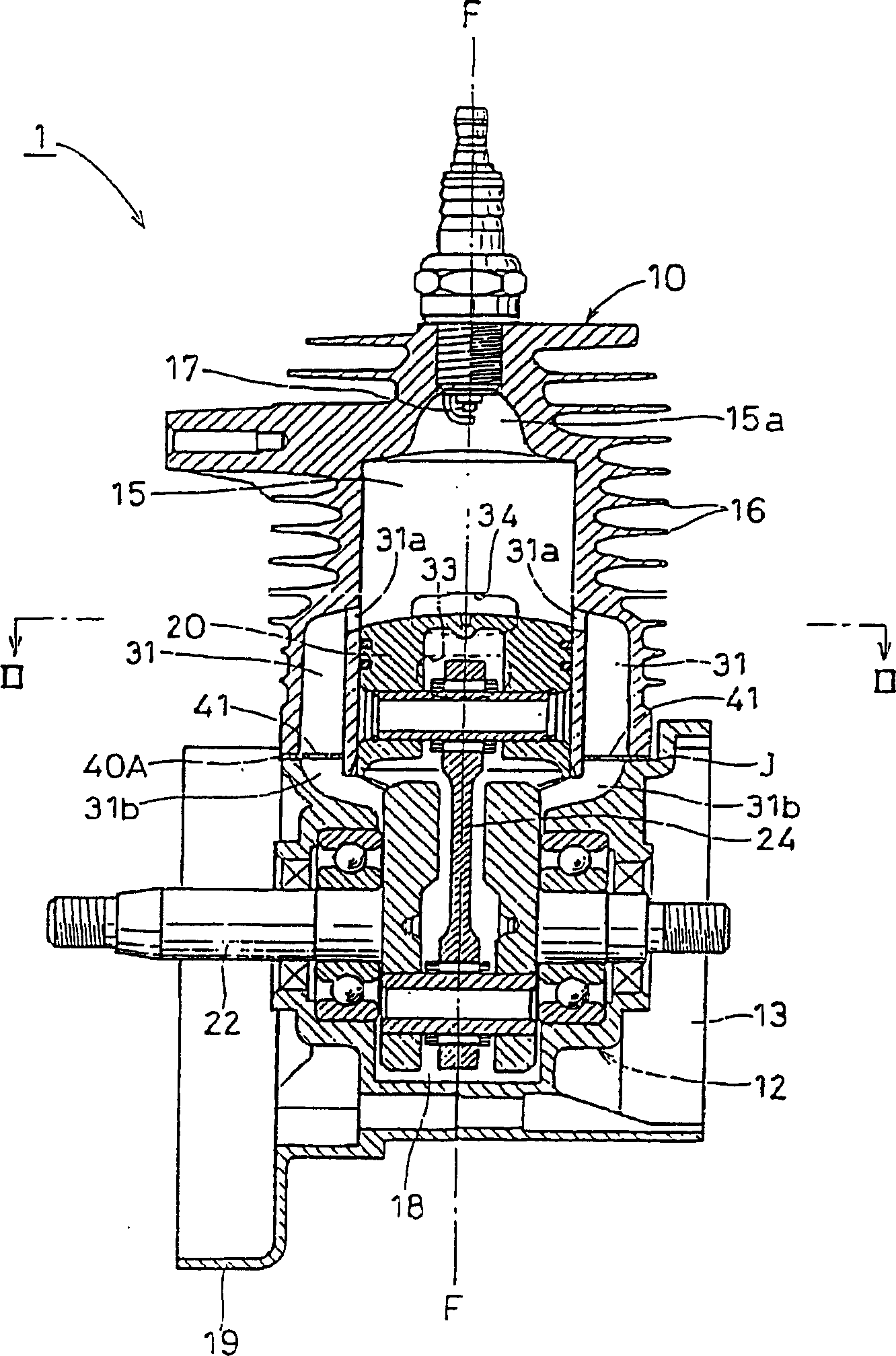
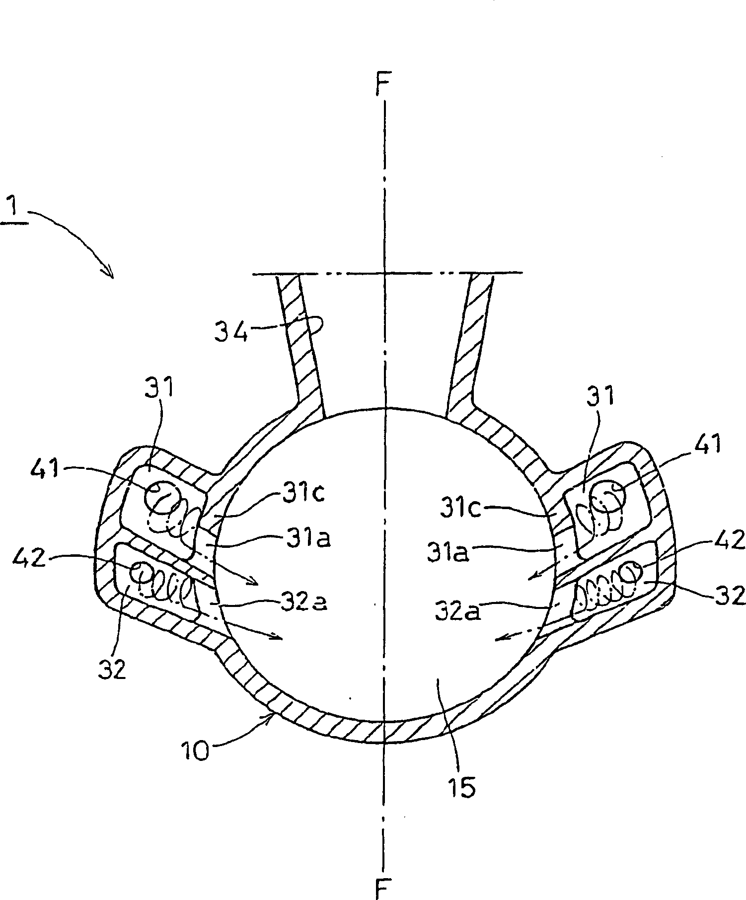
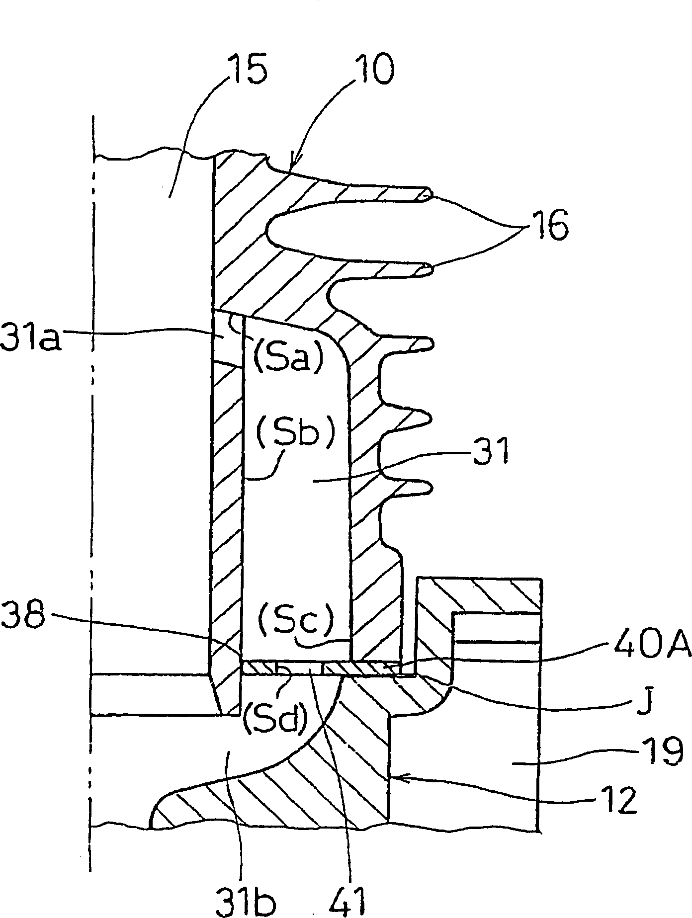
[0032] Such as figure 1 and figure 2As shown, the two-stroke internal combustion engine 1 according to the first embodiment is a small air-cooled two-stroke gasoline internal combustion engine with a four-way scavenging system, which is suitable for use in portable work tools. The engine 1 has a cylinder 10 and a two-piece crankcase 12, in which a piston 20 is accommodated in the cylinder 10, and the crankcase 12 is lined with a cylinder by four through-hole bolts (not shown). Pads 40A (to be described later) are fastened to the lower bottom surface of the cylinder 10, and four bolts are respectively inserted into four diagonal portions of these elements. Below the cylinder 10 , the crankcase 12 encloses a crank chamber 18 . The crankcase 12 rotatably supports a crankshaft 22 for reciprocating the piston 20 up and down through a connecting rod 24 .

[0033] A base part 13 of a recoil starter housing and a base part 19 of a fan housing are integrally connected to the left an...


PUM


Abstract

The invention discloses a two-stroke internal combustion engine, the content of harmful components (such as hydrocarbons) in the exhaust gas is reduced, and the amount of unburned air-fuel mixture can be reduced. The internal combustion engine has a crankshaft located under the piston chamber and a combustion chamber above the piston. One or two pairs of scavenging passages connecting the crankcase and the combustion chamber are arranged, and the pair or two pairs of scavenging passages are arranged symmetrically with respect to the bisecting surface of the exhaust port, thus forming a Schnüller type return scavenging system. Each scavenging channel is throttled close to the scavenging inlet.

Description

technical field [0001] The present invention relates to a two-stroke internal combustion engine suitable, for example, for use in portable power tools. In particular, the present invention relates to a two-stroke internal combustion engine which emits cleaner exhaust gases than many existing two-stroke engines, And can reduce the blowing amount of unburned air-fuel mixture. Background technique [0002] This two-stroke internal combustion engine is usually used in portable power tools such as brush cutters and chainsaws. It includes a cylinder head that cooperates with the piston, a combustion chamber and a crankcase that forms the crank chamber (although the cylinder in the cylinder A chamber may be called a combustion chamber, a working chamber, a cylinder bore, etc., but in this specification, a chamber in a cylinder is generally referred to as a combustion working chamber). An intake port, a scavenging port and an exhaust port are arranged on the barrel part of the cyli...

Claims


Application Information

Patent Timeline
IPC IPC(8): F02B25/16F02B29/00F02B33/04F02B25/14F02B25/20F02B31/04F02B33/44F02B63/02F02B75/02F02D9/02F02F1/22
CPCF02B25/16F02B31/04F02B33/04F02B33/44F02B63/02F02B2075/025F02D2009/0291F02F1/22Y02T10/12
Inventor 福冈敞持塚光次郎山口史郎
Owner KIORITZ
Why Eureka
Try Eureka