
Gullet two stage shaping device of high pressure flexible pipe fixing sleeve

A technology for forming molds and high-pressure hoses, which is applied in the direction of hose connection devices, pipes/pipe joints/pipe fittings, mechanical equipment, etc., and can solve the problem of difficult extension of the extrusion flow direction, reduce the bite of the tooth groove 71, and the vertical extension of the tooth groove 71 Too much and other problems, to achieve good forming strength and increase the effect of contact

Inactive Publication Date: 2006-08-23
慧冈企业有限公司
View PDF0 Cites 0 Cited by
  • Summary
  • Abstract
  • Description
  • Claims
  • Application Information

AI Technical Summary

Problems solved by technology

[0003] However, because the tooth groove is only formed by the stamping die, the actual operation is not as good as expected, such as Figure 9 As shown, the fixed sleeve 70 for forming the tooth groove 71 can also bite the high-pressure hose 73 tightly. However, because the stamping die has too much deformation in one stamping process, the extrusion flow direction is not easy to extend longitudinally with the fixed sleeve 70, and the fixed sleeve 70 is reversely guided. The extrusion flow direction of the tooth grooves 71 is horizontal stacking, causing the tooth grooves 71 to hang down too much, so that the forming area of ​​each tooth groove 71 is large, and the distance between the tooth grooves 71 is reduced (that is, the previous tooth groove 71 is formed by the fixed sleeve. 70 extends from the bottom edge of the root to the top edge of the next tooth groove 71), and relatively narrows the tooth groove 71 to bite and embed the contact surface of the fixed high-pressure hose 73, thus affecting the bite effect of the high-pressure hose 73 and the fixed sleeve 70;
[0004] In addition, the tooth groove 71 is only formed by the stamping die once, and the stamping die concentrates the pressure once, resulting in uneven pressure on the end 712 and the root 711 of the tooth groove 71, and the material structure is different. The end 712 forms a "curled structure". The tissue density at the end 712 is different from that at the root 711. The density at the end 712 is relatively sparse, resulting in poor material strength. It is more likely to be unable to support the load of the embedded high-pressure hose 73, resulting in the deformation of the teeth groove 71.

Method used


Image

  • Gullet two stage shaping device of high pressure flexible pipe fixing sleeve
  • Gullet two stage shaping device of high pressure flexible pipe fixing sleeve
  • Gullet two stage shaping device of high pressure flexible pipe fixing sleeve

Examples


Embodiment Construction

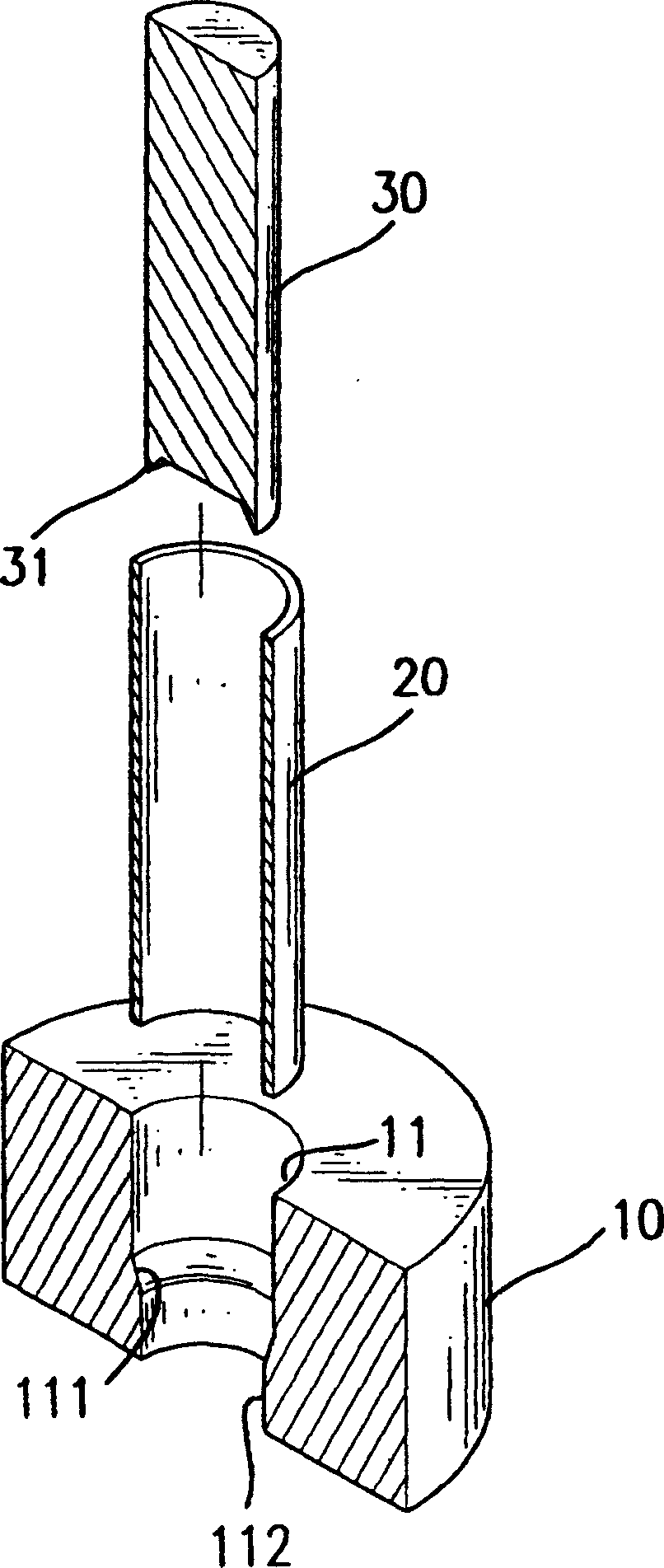
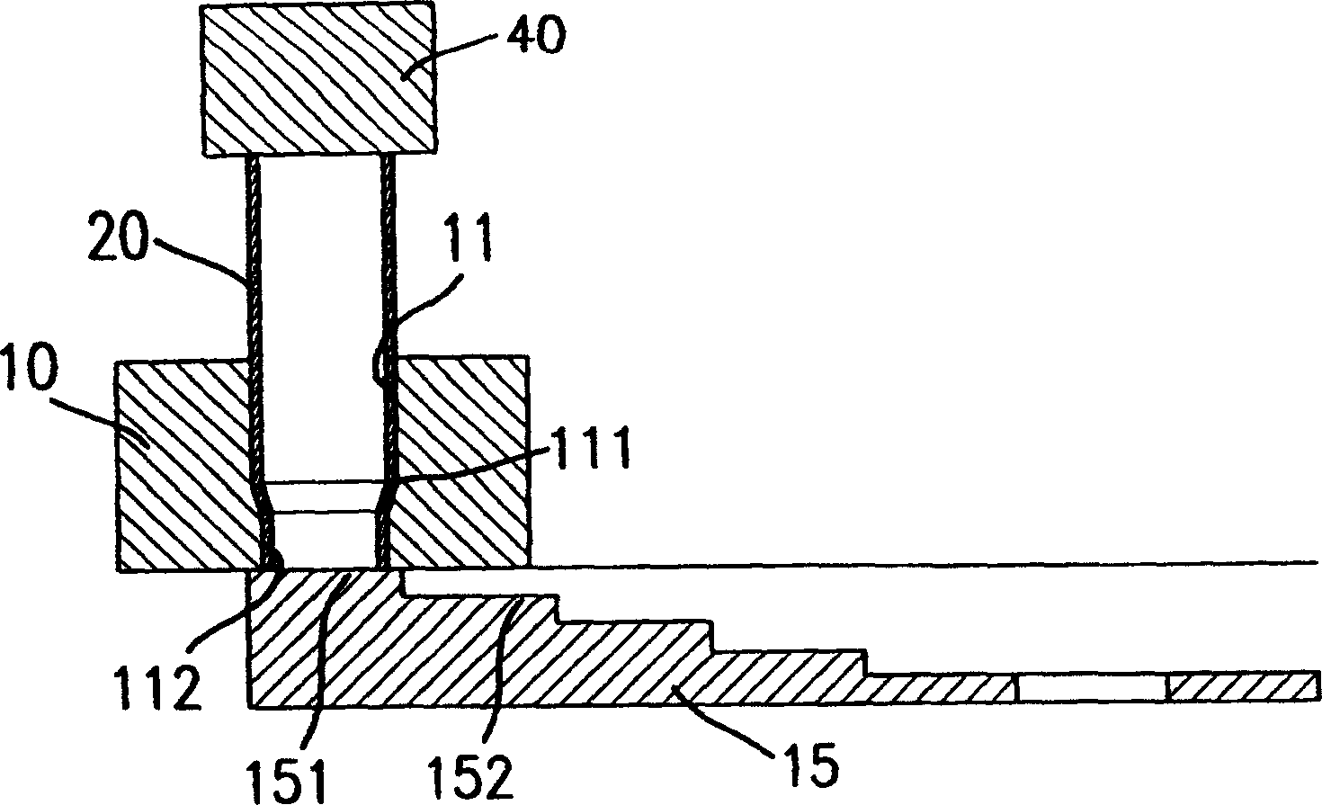
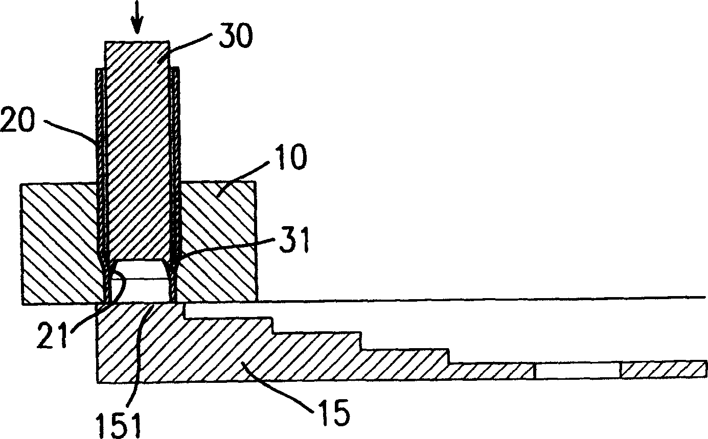
[0035] The present invention is a two-stage forming die device for a high-pressure hose fixed sleeve. Please refer to Figure 1 to Figure 8 , the present invention mainly includes a forming die 30 and a shaping die 50 to carry out a two-stage stamping process on the tooth groove of the fixed sleeve, so that the tooth groove 23 has good strength. The components are described in detail below.

[0036] The forming die 30 such as figure 1 As shown, the forming die 30 is a cylinder, and the axial section protruding downwards at one end peripheral edge has a shearing end 31 like a tiger's tooth; Figure 4 , the shaping die 50 is a cylinder, and an outer diameter is formed at one end than the shaping die 50 column body is a small rectifying pressure end 51.

[0037] Through the two-stage mold design of the present invention, the previous problems can be completely improved in implementation, such as Figure 2 to Figure 5 , which is to illustrate the implementation of using the mol...


PUM


Abstract

The present invention relates to a tool device for forming toothed channel of high-pressure hose fixing cover by adopting two-stage forming process. Said tool device includes a forming mould and a shaping mould. Said invention also provides the process for forming said toothed channel by utilizing said forming mould and shaping mould.

Description

technical field [0001] The invention relates to a two-stage tooth groove forming die device for a fixed sleeve of a high-pressure hose, which relates to the technical field of joints of hydraulic oil pipes, in particular to a mold for forming the tooth groove of a fixed sleeve in a joint. Background technique [0002] At present, the high-pressure hose is connected by a fixed sleeve biting into the inner wall to fix the high-pressure hose. The biting method is that the fixing sleeve uses several teeth grooves formed on the inner wall to embed into the high-pressure hose. And the inventor of the present invention once proposed an invention aiming at the method for forming the tooth groove of the fixed sleeve, such as the invention patent case of "the stamping method for making the tooth groove of the fixed sleeve of the high-pressure hose" with the announcement number 231276 in Taiwan, China. The reference case mainly uses a cylindrical material barrel to be punched into the ...

Claims


Application Information

Patent Timeline
IPC IPC(8): F16L33/207
Inventor 阮金城
Owner 慧冈企业有限公司
Learn More