
Multi-frequency antenna for mobile phone

A mobile phone and antenna technology, applied in the field of multi-frequency mobile phone antennas, can solve the problem of high-frequency antennas ignoring the bandwidth requirements of low-frequency antennas

Inactive Publication Date: 2006-08-09
QUANTA COMPUTER INC
View PDF0 Cites 0 Cited by
  • Summary
  • Abstract
  • Description
  • Claims
  • Application Information

AI Technical Summary

Problems solved by technology

However, this method only considers the high-frequency antenna and ignores the bandwidth requirements of the low-frequency antenna.

Method used


Image

  • Multi-frequency antenna for mobile phone
  • Multi-frequency antenna for mobile phone
  • Multi-frequency antenna for mobile phone

Examples


Embodiment Construction

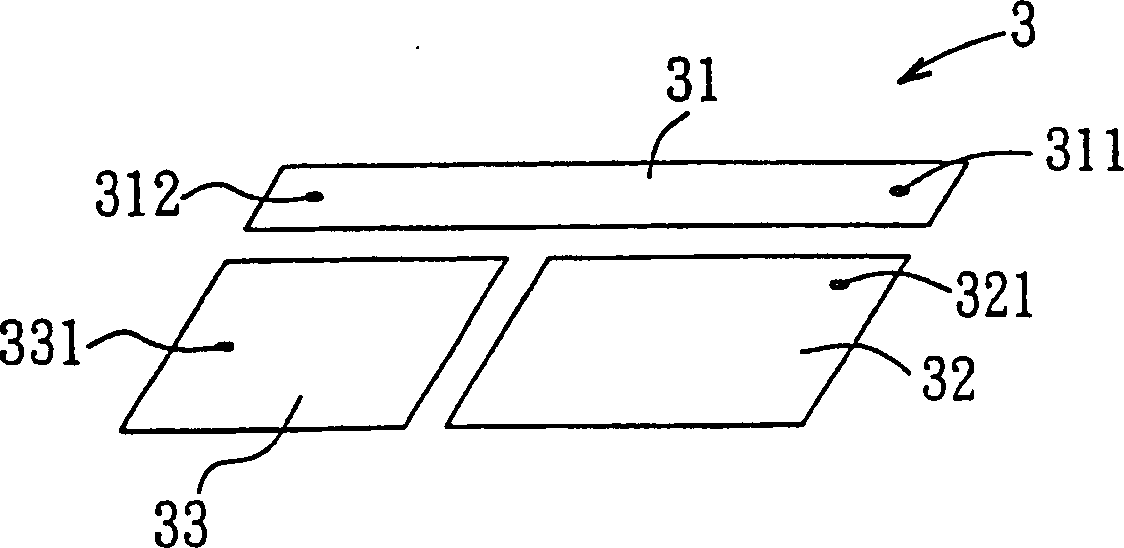
[0015] refer to image 3 Shown is a preferred embodiment of the multi-frequency mobile phone antenna of the present invention. The multi-frequency mobile phone antenna 3 includes a planar loop antenna 31 , a planar antenna 32 and a parasitic element 33 that are coplanar. And in the design of the antenna, the low-frequency carrier signal (900MHz) uses a quarter wavelength (1 / 4λ) as the induction wavelength at resonance, while the high-frequency carrier signal (1800MHz) uses a half-wavelength (1 / 4λ) / 2λ) as the induction wavelength at resonance. Therefore, in the present embodiment, the shape of the planar loop antenna 31 (loop antenna) is designed as a long strip and its area is equivalent to 1 / 2 wavelength of the mobile phone carrier signal. Therefore, the planar loop antenna 31 is an applicable In the high-frequency antenna of the DCS 1800 system, a signal feed-in point 311 and a ground point 312 are respectively provided at opposite ends of the planar loop antenna 31, which...


PUM


Abstract

The invention provides a multiple frequency mobile phone antenna, comprising a flat-plate antenna as low frequency antenna, a flat surface type return circuit antenna as high-frequency antenna adjacent to the flat-plate antenna, and a parasitic element inter-coupling the plate antenna adjacent the flat-plate antenna and flat surface type return circuit antenna, thus the influence to the antenna gain by the grounding earth surface of the mobile phone can be reduced, and the frequency width for the high-frequency and low-frequency antenna can be increased.

Description

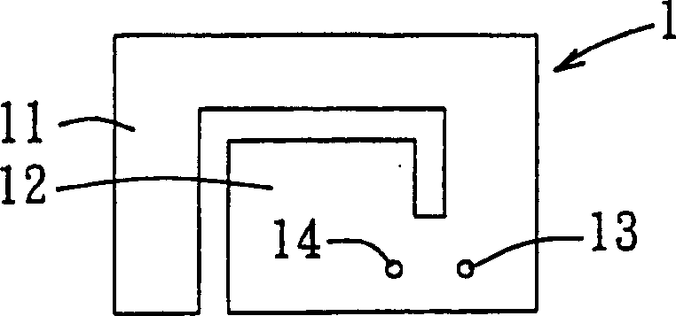
technical field [0001] The invention relates to a mobile phone antenna, in particular to a multi-frequency mobile phone antenna which can reduce the influence of the ground plane of the mobile phone on the gain of the antenna and simultaneously increase the bandwidth of the antenna. Background technique [0002] Nowadays, in order to meet the requirements of thinness, shortness and beauty, a hidden antenna has been developed in the mobile phone, and in order to reduce the antenna’s occupation of the internal space of the mobile phone, a hidden planar antenna has been developed, and the planar antenna Whether the design is good or not often determines the communication quality of the mobile phone. like figure 1 As shown, it is a traditional inverted F-shaped planar antenna 1, which forms a bent cutting groove on a thin metal plate 1, and divides the thin metal plate into a first antenna part 11 and a second antenna part 12. , making the first antenna part 11 a low-frequency...

Claims


Application Information

Patent Timeline
Patent Type & Authority Patents(China)
IPC IPC(8): H01Q1/38H01Q1/27H01Q5/00H01Q13/08H01Q5/28H01Q5/378
Inventor 蔡调兴彭奂喆施凯
Owner QUANTA COMPUTER INC
Learn More