Front and rear wheel brake interlinking device for vehicle

A linkage device and brake technology, which is applied to bicycle brakes, motor vehicles, bicycles, etc., can solve the problems of reduced transmission efficiency of steering force, and achieve the effect of suppressing the reduction of transmission efficiency and suppressing the reduction of transmission efficiency

Inactive Publication Date: 2006-02-08
HONDA MOTOR CO LTD
View PDF1 Cites 1 Cited by
  • Summary
  • Abstract
  • Description
  • Claims
  • Application Information

AI Technical Summary

Problems solved by technology

[0003] However, in the brake device with the brake lever and the brake pedal as the object of the present invention, since the distance between the brake lever and the brake pedal is very long, when the original interlocking device is used for the brake device, Not only does it need to arrange a long interlocking brake cable between the brake lever and the brake pedal, but it is also unsatisfactory because the transmission efficiency of the steering force is reduced due to the arrangement of the cable with many bends.

Method used


Image

  • Front and rear wheel brake interlinking device for vehicle
  • Front and rear wheel brake interlinking device for vehicle
  • Front and rear wheel brake interlinking device for vehicle

Examples


Embodiment Construction

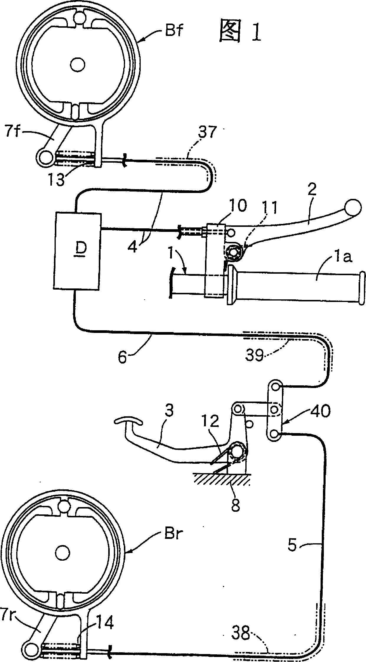
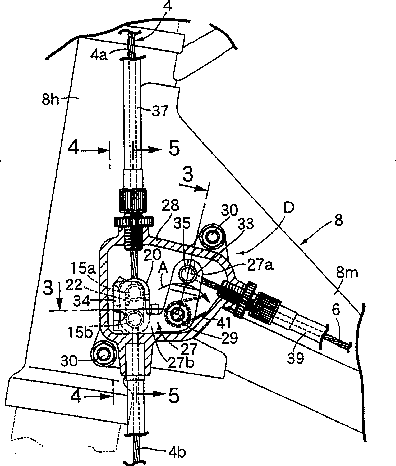
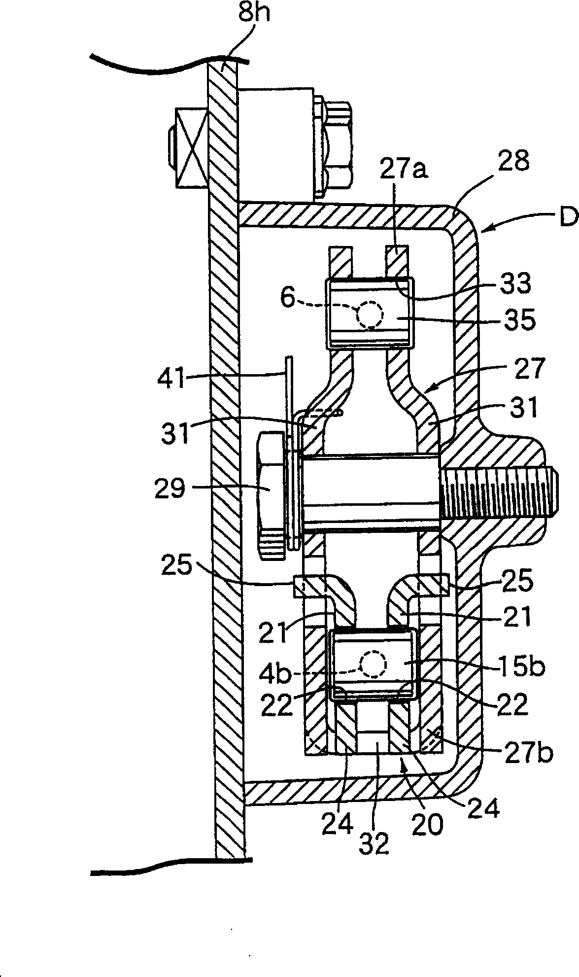
[0022] Embodiments of the present invention will be described below based on the embodiments of the present invention shown in the drawings.

[0023] Fig. 1 is an overall schematic diagram of a brake device for a motorcycle having a front and rear wheel brake interlocking device according to the present invention. figure 2 It is a side view of main parts of the aforementioned front and rear brake interlocking device. image 3 yes figure 2 The 3-3 line enlarged section view. Figure 4 yes figure 2 The 4-4 line enlarged section view. Figure 5 yes figure 2 The 5-5 line enlarged section view. Figure 6 It is an exploded perspective view of main parts of the above-mentioned front and rear brake interlocking device.

[0024] First, in Fig. 1, a rod support 10 is fixedly installed adjacent to its right sleeve 1a on the operating handle 1 of the motorcycle, on which the brake lever 2 is pivotally supported. Lever 2 is connected with the actuating lever 7f of drum type front br...


PUM


Abstract

The invention provides an interlocking device of simple constitution capable of operating a front wheel brake as well as a rear wheel brake when operating a brake pedal in a motorcycle. A joint member 20 is mounted to an intermediate part of a front brake wire 4, and a bell crank 27 is journalled to a cover 28 fastened to a head pipe 8a, in proximity to the joint member 20. A first arm 27a is connected to the brake pedal 3 through an interlocking brake wire 6, and a second arm 27b is placed facing the joint member 20 so as to abut on and separate from it. When pulling the interlocking brake wire 6 by the brake pedal 3, the bell crank 27 moves the joint member 20 in the operating direction of the front brake Bf, and when pulling the front brake wire 4 by a brake lever 2, the joint member 20 is separated from the bell crank 27.

Description

technical field [0001] The invention relates to a front and rear wheel brake linkage device for a vehicle. Background technique [0002] In the existing braking device for motorcycles, the left brake lever and the right brake lever respectively pivotally support the left end and the right end of the joystick, and the right brake lever passes through the front brake cable and the front wheel brake. The actuating lever of the left brake lever is connected with the actuating lever of the rear brake through the rear brake cable. Simultaneously, the right brake lever is acted by pulling the interlocking brake cable through the equalizer bar, thereby making the front wheel brake action, and such front and rear wheel brake interlocking devices are well known (with reference to JP 9-58434 No.). [0003] However, in the brake device with the brake lever and the brake pedal as the object of the present invention, since the distance between the brake lever and the brake pedal is very ...

Claims


Application Information

Patent Timeline
Patent Type & Authority Patents(China)
IPC IPC(8): B62L3/08B62L3/00
CPCB62K3/12B62L1/08B62L3/02
Inventor 冈崎泰典
Owner HONDA MOTOR CO LTD
Why Eureka
Try Eureka