Six freedom parallel mechanism for virtual shaft digitally controlled machine tool and measuring machine

A technology of numerically controlled machine tools and virtual axes, applied in the direction of mechanical measuring devices, measuring devices, mechanical devices, etc., can solve problems such as complex manufacturing and assembly, complex structure, and difficult kinematics solutions

Inactive Publication Date: 2005-09-21
JIANGSU POLYTECHNIC UNIVERSITY
View PDF0 Cites 1 Cited by
  • Summary
  • Abstract
  • Description
  • Claims
  • Application Information

AI Technical Summary

Problems solved by technology

The Stewart mechanism and its improved mechanism have the following disadvantages: ① It is difficult to solve the kinematics forward solution; ② The position and direction of the motion platform are strongly coupled; ③ The movement space is small; ④ It is difficult to manufacture high-precision ball pairs
[0003] ①The kinematics positive solution is an 8-degree closed solution, and a one-dimensional 8-degree equation needs to be established and solved, which makes the control and trajectory planning of the system more complicated
②The motion input and output of the three-dimensional translation mechanism are strongly coupled, which makes the system control very complicated
③ There are virtual constraints in the mechanism, making its manufacture and assembly more complicated
④The working space is still relatively small
For the 6-SPS and 6-RSS mechanisms, since the movable platform has 6 spatial degrees of freedom relative to the base platform, the spatial pose of the end effector is relatively flexible, but due to the relatively complicated structure of the mechanism, Fewer space constraints make it difficult to solve the end effector
Since the above-mentioned structures contain more spherical pairs, their manufacture and assembly are more complicated.

Method used


Image

  • Six freedom parallel mechanism for virtual shaft digitally controlled machine tool and measuring machine
  • Six freedom parallel mechanism for virtual shaft digitally controlled machine tool and measuring machine
  • Six freedom parallel mechanism for virtual shaft digitally controlled machine tool and measuring machine

Examples


Embodiment Construction

[0014] The technology of the present invention will be further described below by means of accompanying drawings and examples.

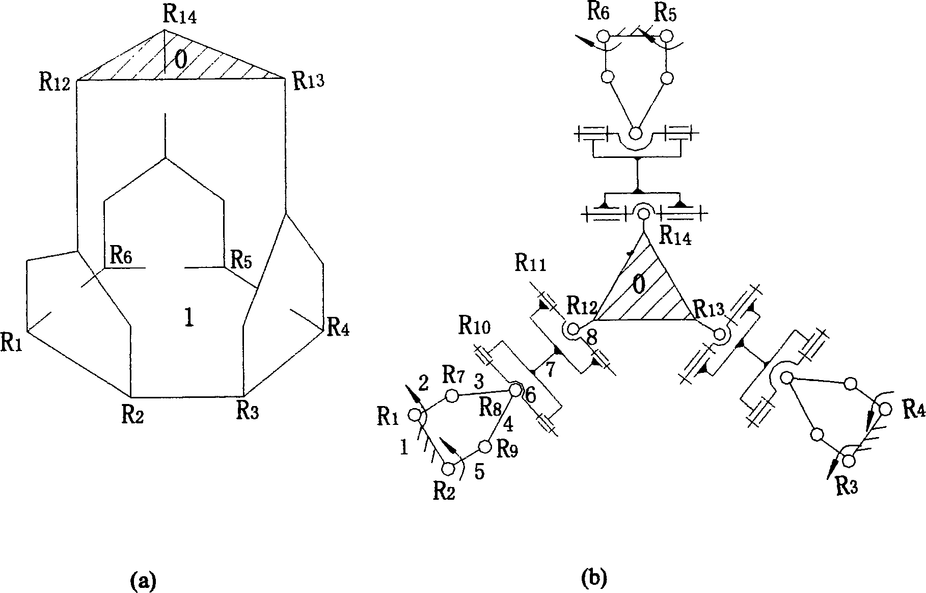
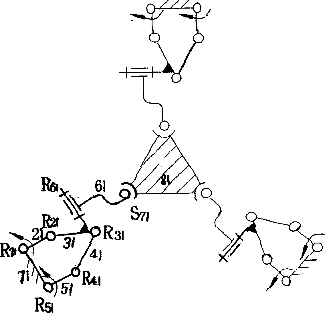
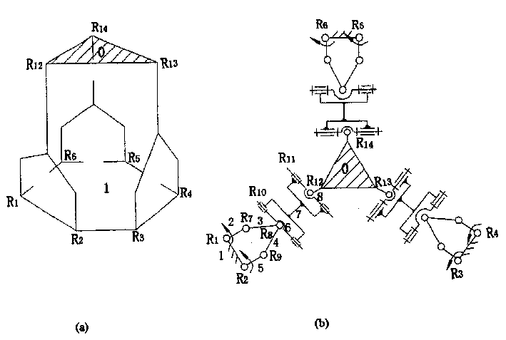
[0015] ①, attached figure 1 It is a schematic structural diagram of the six-degree-of-freedom parallel mechanism of the present invention, figure 1 (a) is a three-dimensional stereogram of the parallel mechanism, figure 1 (b) is its two-dimensional plane expansion diagram. It consists of an upper moving platform 0, a lower static platform 1 and three connecting legs with the same structure connecting the upper and lower platforms. Each connecting leg is a hybrid chain, including a five-bar 1, 2, 3, 4, 5 passing through five revolving pairs R 1 , R 7 , R 8 , R 9 , R 2 A planar closed-circuit structure composed of connections and two rotating pairs R composed of components 6, 7, and 8 parallel to each other through axes 10 , R 11 The open-chain structure formed; the member 6 of the open-chain structure and the members 3 and 4 of the planar ...


PUM


Abstract

The six freedom parallel mechanism consists of moving platform, static platform and three connecting legs between the moving platform and the static platform. Each of the connecting legs consists of one planar closed-loop structure and one open-loop structure, the planar closed-loop structure consists of five rods and five rotation pairs with one member being one part of the static platform; and the open-loop structure consists of three members and two rotation pairs with parallel axes, with one end member constituting one composite hinge together with the two members in the planar closed-loop structure and the other end member being connected to the moving platform mechanically via one rotation pair. Controlling the motion of six driving joints in the static platform can control the position and posture of the moving platform in space to realize 3D translation and 3D rotation output. The moving platform may be used as the executing mechanism of virtual shaft digitally control machine tool, etc.

Description

technical field [0001] The present invention relates to a class of executive mechanisms of machine tools, robots and coordinate measuring machines, and specifically provides a class (two types) of new six-degree-of-freedom parallel mechanisms for parallel-structured virtual axis numerical control machine tools, parallel coordinate measuring machines and parallel robots . Background technique [0002] Parallel structure CNC machine tool refers to the machine tool with parallel mechanism as the executive mechanism. This machine tool is considered to be a revolution in the structure of machine tools since the 20th century. At present, prototypes of this machine tool have been developed in the United States, Japan, China and other countries, and most of the parallel mechanisms used are traditional Stewart mechanisms or their improved mechanisms. This mechanism for controlling the position and attitude of the tool in space is mainly composed of a base, a moving platform and a co...

Claims


Application Information

Patent Timeline
Patent Type & Authority Patents(China)
IPC IPC(8): B23Q41/04B25J9/08G01B5/004
Inventor 沈惠平杨廷力马履中
Owner JIANGSU POLYTECHNIC UNIVERSITY
Why Eureka
Try Eureka