
Washing machine

A washing machine and detergent technology, applied in the field of washing machines, can solve the problems of unautomated detergent input method, labor saving, soiling the ground, knocking down, etc.

Inactive Publication Date: 2005-08-31
PANASONIC CORP
View PDF0 Cites 2 Cited by
  • Summary
  • Abstract
  • Description
  • Claims
  • Application Information

AI Technical Summary

Problems solved by technology

[0006] In this existing structure, in the case of washing detergent according to the amount of laundry or the amount of water supplied each time the detergent is added, whether it is a powder detergent or a liquid detergent, it must be transported in a commercially available container. Put it in the vicinity of the washing machine, otherwise, it will spill on the floor or some parts of the washing machine's control device, and there are defects in the safety of the operation.
In addition, since the metering is mostly carried out visually, there will be errors in the input amount, so that there are operational defects such as insufficient cleaning power and waste of detergent.
[0007] Recently, among washing machines, fully automatic washing machines that automatically determine the amount of water and perform washing steps are becoming mainstream, and are promoting labor-saving housework. However, it is inconvenient to measure and input only the detergent each time.
[0008] In addition, there are concerns about storage such as children swallowing detergent by mistake during storage, or liquid detergents flowing out of the container when they are put in or being knocked over during storage and soiling the floor, etc.
[0009] As mentioned above, in the washing operation, there is also a problem that automation and labor saving have not been practically realized by only the method of adding detergent.

Method used


Image

  • Washing machine
  • Washing machine
  • Washing machine

Examples


Embodiment 1

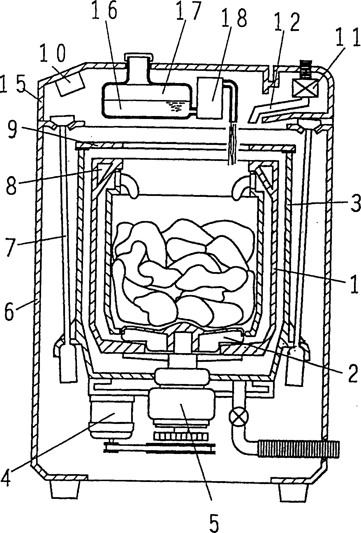
[0043] Such as figure 1 As shown, the housing cover 15 covers the upper part of the housing 6, and is provided with a control device 10, a water supply valve 11, a water supply pipeline 12, and the like. A detergent tank 17 is provided inside the housing 15, and accommodates liquid detergent 16 in an amount capable of at least two washes. Detergent input device 18 is used to inject liquid detergent 16 in detergent box 17 into washing and dehydration tank 1, and is composed of manual pump, automatic pump, liquid (gas) pressure cylinder, etc., and is controlled and operated by control device 10.

[0044] In the above-mentioned structure, the liquid detergent 16 that can be used for at least twice washing is placed in the detergent box 17, and the detergent box 17 is installed in the outer casing 15, and the laundry is dropped into the washing and dehydrating tank 1 When the internal operation is started, the control device 10 drives the detergent input device 18 to inject a pr...

Embodiment 2

[0048] figure 1 The control device 10 shown has a cloth amount judging device (not shown) for judging the amount of laundry (clothes) thrown into the washing and dehydrating tank 1, and according to the result of judging by the cloth amount judging device, that is, according to the amount of laundry According to at least one parameter of the amount of water or the amount of water suitable for the amount of laundry, operate the detergent input device 18, and put the liquid detergent 16 into the washing and dehydrating tank 1. Other structures are the same as the above-mentioned embodiment 1.

[0049] In the above structure, when the laundry is put into the washing and dehydrating tank 1 to start operation, the control device 10 drives the motor 4 to rotate the agitating blade 2, and judges according to the degree of deceleration of the motor 4 in the inertial operation after the power supply to the motor 4 is cut off. The amount of laundry in the washing and dehydrating tank ...

Embodiment 3

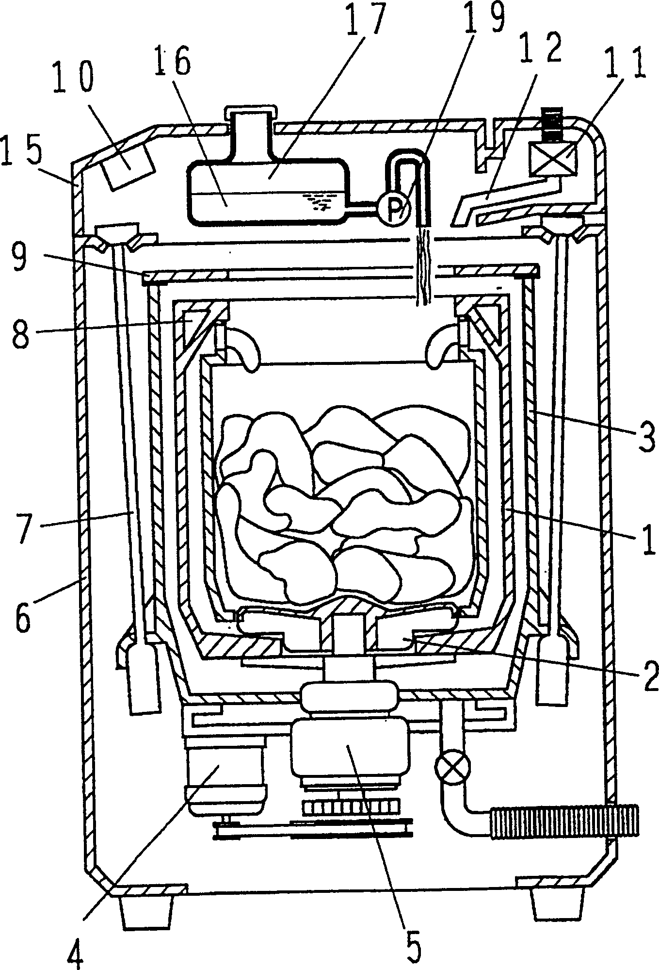
[0052] Such as figure 2 As shown, the pump device 19 constitutes a detergent input device, and is composed of a pump device that directly sucks liquid detergent, such as a centrifugal pump or a gear pump. Other structures are the same as the above-mentioned embodiment 1 or 2.

[0053] In the above structure, when the laundry is put into the washing and dehydrating tank 1 to start operation, the control device 10 drives the motor 4 to rotate the agitating blade 2, and judges according to the degree of deceleration of the motor 4 in the inertial operation after the power supply to the motor 4 is cut off. The amount of laundry in the washing and dehydrating tank 1. Based on the determination result, the pump device 19 is operated, and the liquid detergent 16 is injected into the washing and dehydrating tank 1 in an amount corresponding to the laundry in the washing and dehydrating tank 1 .

[0054] Thereafter, the operation of the motor 4 and the water supply valve 11 is contr...


PUM


Abstract

A washer, provided with a detergent putting device for putting in the washing and dehydrating drum a liquid detergent, can eliminate an inconvenience in treatment at the time of putting the detergent in the drum, and an inconvenience in storage of the detergent, and automatically put detergent and improve an operationability. An upper part of a water receiving tank 3 having a washing and dehydrating drum 1 rotatably arranged therein is covered with a water receiving tank cover 9. An outer shell cover 15 is provided on the upper part of an outer shell 6 for preventing a vibration and supporting the water receiving tank so as to cover the water receiving tank 3 therewith. In the outer shell cover 15, a detergent tank 17 capable of housing an amount of liquid detergent 16 which can be used for washing at least twice is provided. The liquid detergent 16 is put in the washing and dehydrating drum 1 by a detergent putting device 18.

Description

technical field [0001] The present invention relates to a washing machine provided with a detergent injecting device for injecting liquid detergent into a washing and dehydrating tank. Background technique [0002] Currently, washing machines such as Figure 12 constituted as shown. The structure is described below. [0003] Such as Figure 12 As shown, a rotatable stirring blade 2 is arranged on the bottom surface of the washing and dehydrating tank 1 , and a water tank 3 is provided outside the washing and dehydrating tank 1 . A motor 4 for driving the washing and dehydrating tank 1 and the agitating blade 2 is installed on the bottom surface of the water tank 3, and the washing and dehydrating tank 1 or the agitating blade 2 is driven through a clutch device 5 for switching the driving part. The water tank 3 is mounted on the housing 6 in a vibration-isolated manner via a suspension 7 . A fluid balancer 8 containing liquid is fixed on the top of the washing and dehydra...

Claims


Application Information

Patent Timeline
IPC IPC(8): D06F39/02
CPCD06F39/022D06F39/088D06F34/18D06F33/37D06F39/081D06F39/14D06F2103/04D06F2105/42
Inventor 今井俊次朝见直西田一夫
Owner PANASONIC CORP
Learn More