Flexible rotor low speed holographic dynamic balancing method

A technology of flexible rotor and rigid rotor, applied in the field of holographic dynamic balance, to achieve the effect of improving dynamic balancing efficiency, improving balancing accuracy, and reducing the number of times of trial weight lifting

Inactive Publication Date: 2005-06-01
XI AN JIAOTONG UNIV
View PDF2 Cites 1 Cited by
  • Summary
  • Abstract
  • Description
  • Claims
  • Application Information

AI Technical Summary

Problems solved by technology

[0003] As mentioned above, the traditional low-speed balance can only balance the rotor in the rigid mode; when the operating speed exceeds the first-order critical speed, the new unbalance of the rotor in the flexible mode needs to be balanced by high-speed dynamic balancing

Method used


Image

  • Flexible rotor low speed holographic dynamic balancing method
  • Flexible rotor low speed holographic dynamic balancing method
  • Flexible rotor low speed holographic dynamic balancing method

Examples


Embodiment

[0084] Balance scheme 1: Prioritize the balance force component

[0085] The balancing procedure for prioritizing the balancing force components is as follows: Figure 4 As shown, the specific description is as follows:

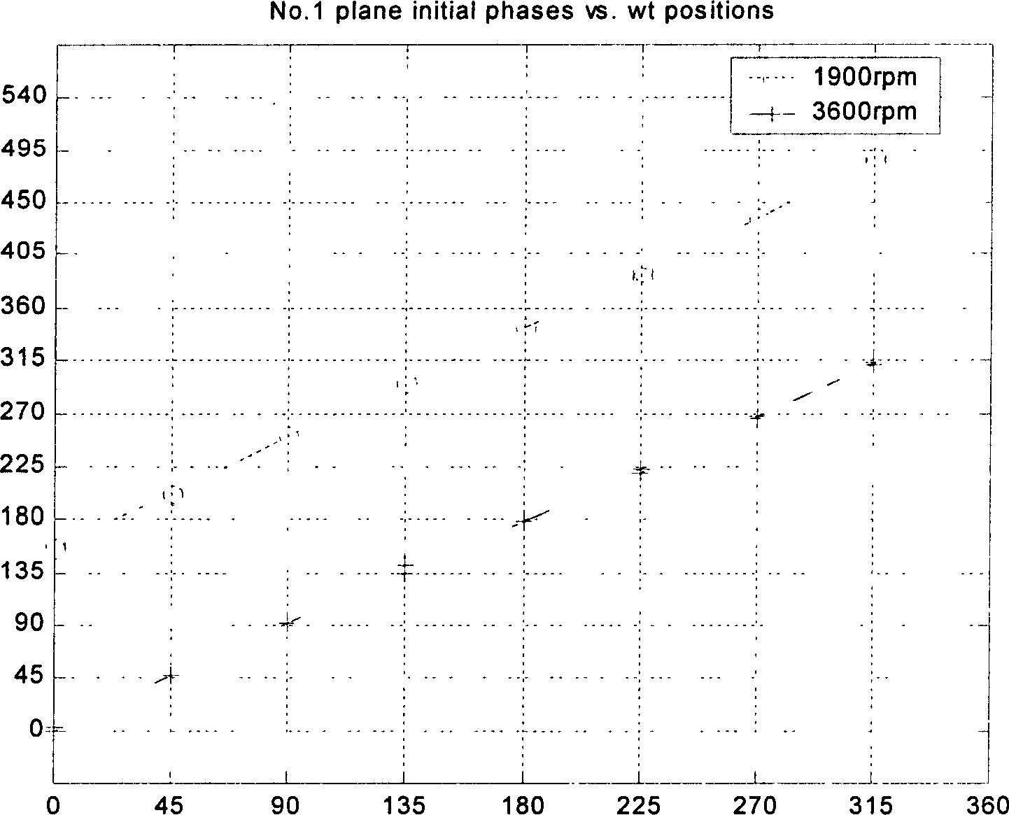
[0086]1. Measure the basic data. The working speed of the rotor is Ω=3600rpm, and the vibration at the working speed before shutdown is measured; the Bode diagram of the rotor shutdown process is obtained in the experiment, and ω=1900rpm is selected as the balance speed lower than the first-order critical value of the rotor; the measurement test bench is in The vibration in the cranking state is used as the runout, and the shaft vibration value must be deducted from the original runout; measure the original vibration of the rotor when ω=1900rpm (sampling frequency 2kHz, filter 1kHz, sampling points 2048);

[0087] 2. After subtracting the original beating from the vibration data, make a three-dimensional holographic spectrum to obtain the initial phase point...


PUM


Abstract

The invention discloses a low-speed holographic dynamic balancing method for a flexible rotor in the field of vibration diagnosis and control of rotating machinery. Based on the holographic spectrum information integration principle and system theory, the three-dimensional holographic spectrum method is used to comprehensively describe the first-order critical speed of the flexible rotor. The change law of the front and rear vibration behavior, with the low speed lower than the first-order critical speed as the balance speed, realizes the balance of the second-order mode of the flexible rotor at the working speed higher than the first-order critical speed. This method breaks through the limitation that the traditional low-speed balancing method can only be applied to rigid rotors, and provides a scientific basis and means for balancing flexible rotors at low speeds.

Description

1. Technical field [0001] The invention belongs to the technical field of rotor dynamic balance, and further relates to the field of fault diagnosis and control of rotating machinery, in particular, it is mainly used to achieve a flexible rotor at a working speed higher than the first-order critical speed at a balance speed lower than the first-order critical speed of the rotor. Holographic dynamic balancing method for second-order modes. 2. Background technology [0002] Due to the different working speed, structure and rigidity of rotors and the different balance precision requirements of various rotors, rigid rotor balance and flexible rotor balance can be used to obtain the required balance precision of the rotor. When the working speed of the rotor is much lower than the first-order critical speed of the rotor, and the influence of the rotor deflection on its balance can be ignored, it can be called a rigid rotor; on the contrary, when the additional unbalance caused by...

Claims


Application Information

Patent Timeline
Patent Type & Authority Patents(China)
IPC IPC(8): G01M1/16
Inventor 屈梁生刘石张西宁
Owner XI AN JIAOTONG UNIV
Why Eureka
Try Eureka