
Low-speed orthogonal fusion dynamic balance method for composite tail shaft on dynamic balance machine

A composite material and dynamic balancing machine technology, which is applied in the field of rotating shaft dynamic balancing, can solve problems such as complex operation, insufficient balance accuracy, and inability to perform dynamic balance tests

Active Publication Date: 2021-09-07
CHONGQING UNIV
View PDF12 Cites 0 Cited by
  • Summary
  • Abstract
  • Description
  • Claims
  • Application Information

AI Technical Summary

Problems solved by technology

[0004] 1) The balance accuracy is insufficient when carrying out the balance test for anisotropic composite materials;
[0005] 2) During the test process, it is necessary to start and stop multiple times, or formulate a corresponding balance plan, and the operation is complicated;
[0006] 3) Compensation must be performed when synthesizing the initial phase point, and there are problems of difficulty and accuracy;
[0007] 4) The dynamic balance test cannot be carried out for the rotor whose vibration amplitude is too large at the critical speed;
[0008] 5) Vibration acceleration sensors are often installed on dynamic balancing machines for dynamic balance testing, while eddy current displacement sensors are difficult to install

Method used


Image

  • Low-speed orthogonal fusion dynamic balance method for composite tail shaft on dynamic balance machine
  • Low-speed orthogonal fusion dynamic balance method for composite tail shaft on dynamic balance machine
  • Low-speed orthogonal fusion dynamic balance method for composite tail shaft on dynamic balance machine

Examples


Embodiment Construction

[0040] In order to make the implementation process of the present invention more detailed and understandable, the technical solution of the present invention will be described in detail below in conjunction with the examples of the present invention. Obviously, the embodiments described herein are only certain embodiments of the present invention. Rather than all embodiments of the present invention. Based on the embodiments of the present invention, all other embodiments obtained by those skilled in the art without making creative efforts belong to the protection scope of the present invention.

[0041] According to the technical solution of the present invention, the low-speed orthogonal fusion dynamic balancing method of the composite material tail shaft on the dynamic balancing machine of the present invention is different from other dynamic balancing methods, and has a significant balancing effect on the balance of the composite material shaft. The following example is a c...


PUM


Abstract

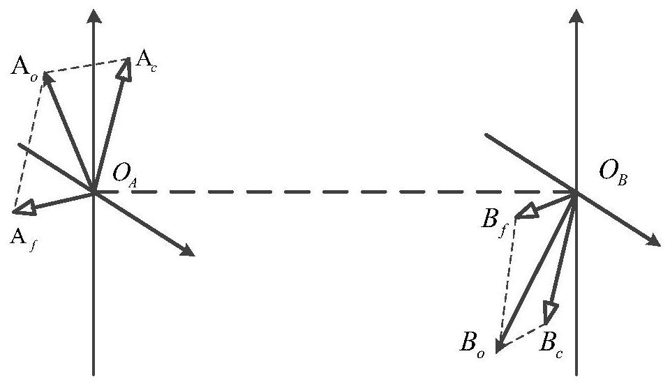
The invention discloses a low-speed orthogonal fusion dynamic balancing method for a composite tail shaft on a dynamic balancing machine. The method comprises the following steps: balancing a rotating shaft workpiece at a low speed, fusing vibration signals by using an orthogonal fusion technology, and performing force and couple decomposition on the synthesized signals, wherein only one time of trial weight is needed, and the trial weight needs to contain force and couple components at the same time; carrying out force and couple decomposition on the added test mass, and carrying out force and couple decomposition on the vibration data after the test mass is added; calculating force and couple response after mass test, and calculating the magnitude and phase of the required balance mass; and adding the required balance mass to reach a balance index, and ending the balance. Compared with other dynamic balance methods, the method has the advantages that the number of times of trial weight is small, the required balance rotating speed is lower than the first-order critical rotating speed, the balance effect on the anisotropic composite material shaft is remarkable, and the method has good engineering applicability.

Description

technical field [0001] The invention belongs to the technical field of rotating shaft dynamic balance, and further relates to the field of fault diagnosis and signal processing of rotating machinery. Background technique [0002] Rotating machinery is used extensively in the aviation industry and is a staple product in many manufacturing sectors. They use rotating shafts and other rotating parts as the main body of their work. Once an accident occurs, huge losses will be caused. At present, the widely used dynamic balancing techniques mainly include influence coefficient method, mode shape method, holographic method and so on. The tail shaft of composite materials is anisotropic, that is, the damping or stiffness in each direction is different. This anisotropy mainly comes from the material properties and other reasons. At the same time, due to the manufacturing process and other reasons, the initial unbalance of the composite tail shaft is very large, and it is difficult ...

Claims


Application Information

Patent Timeline
Patent Type & Authority Applications(China)
IPC IPC(8): G01M1/16
CPCG01M1/16Y02T90/00
Inventor 柏林李飞崔图苗福华刘小峰陈兵奎
Owner CHONGQING UNIV
Learn More