
Gas shielded welding device

A technology of shielding gas and welding device, which is applied in the directions of tin feeding device, welding equipment, welding equipment, etc., can solve the problem that the oxygen concentration of the inert shielding gas cannot be fully reduced, and achieve the effect of improving the effect.

Inactive Publication Date: 2005-05-04
NIHON DEN NETSU KEIKI CO LTD
View PDF3 Cites 0 Cited by
  • Summary
  • Abstract
  • Description
  • Claims
  • Application Information

AI Technical Summary

Problems solved by technology

[0006] Utilize the technology and Figure 12 , 13 The technology of the Japanese Patent Application Laid-Open No. 7-185790 has the problem that the inert gas ejected from the nozzle at a high speed and strong force entrains the surrounding atmosphere into the air flow. As a result, the inert gas in the formed inert protective gas cannot be sufficiently reduced oxygen concentration
[0007] In addition, in the technology of Japanese Patent Laid-Open No. 8-130365, there is also such a problem that the inert gas ejected from the gas nozzle at a high speed and powerfully engulfs the protective gas in the cover, and at the same time, the atmosphere is drawn in from the inlet and outlet. Intruded into the cover, these gases flow up and down violently, are stirred and mixed together, and as a result, the oxygen concentration in the inert protective gas cannot be sufficiently reduced

Method used


Image

  • Gas shielded welding device
  • Gas shielded welding device
  • Gas shielded welding device

Examples


Embodiment Construction

[0061] Embodiments of the present invention will be described in detail below with reference to the drawings.

[0062] (1) Embodiment of the airflow control device

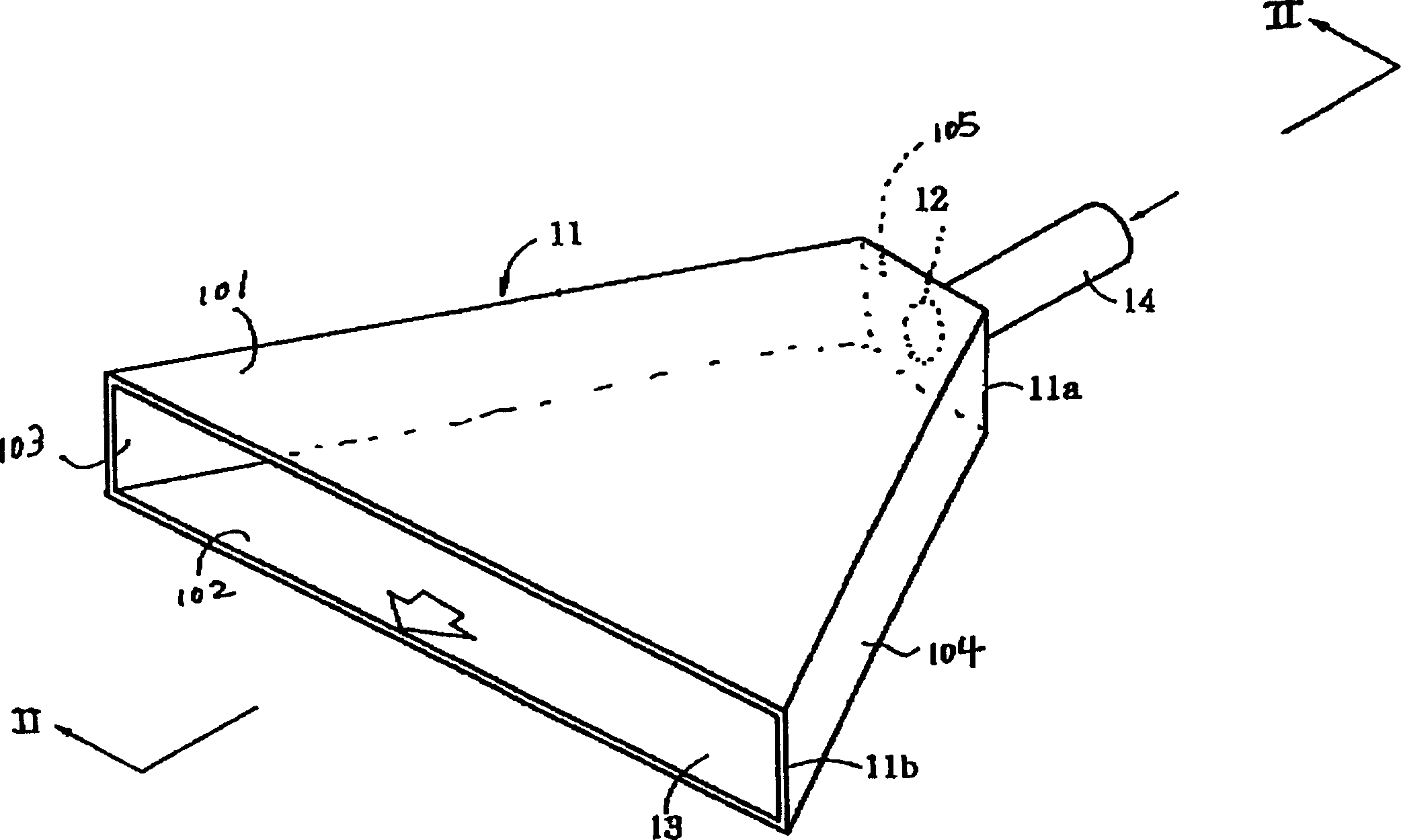
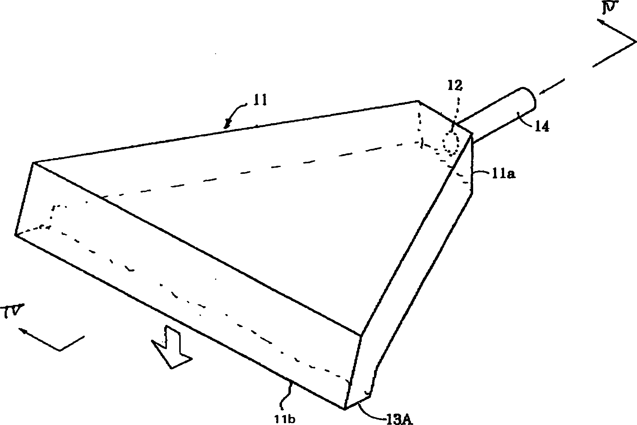
[0063] figure 1 It is an oblique view of the overall view of the first embodiment of the air flow control device of the present invention; image 3 It is a perspective view of the overall view of the second embodiment of the air flow control device of the present invention. in addition, figure 2 is along figure 1 The side sectional view of the II-II line; Figure 4 is along image 3 Side sectional view of line IV-IV. That is, in these figures, the air supply port is formed on the converging end portion 11a of one side of the radial air supply port frame 11 composed of a pair of upper and lower walls 101, 102, a pair of side walls 103, 104, and a rear wall 105. 12, and connect the air supply pipe 14, supply N 2 (nitrogen) and other inert gases. On the upper and lower walls 101 , 102 of the air inlet fra...


PUM


Abstract

The invention discloses a gas flow control device and a welding device using it. It will not involve protective gas such as the atmosphere, reduce the supply of inert gas, and can also form a high concentration of inert protective gas in the welding device. A gas supply port is formed radially at the converging end on one side, and a gas discharge port is formed at the other end. The cross-sectional area of ​​the flow path of the inert gas flowing from the gas supply port to the gas discharge port gradually increases. The flow path forms a serpentine flow path, and an inert gas is supplied from the vent port of the gas supply port frame to the area where the molten solder contacts the printed circuit board to form an inert shielding gas.

Description

technical field [0001] The present invention relates to a gas flow control device and a welding device utilizing the same. Background technique [0002] For example, if molten metal is placed in the air due to its high temperature, its surface will oxidize, which is not good. In this case, an inert gas is supplied to the surface of the molten metal to form an inert shielding gas that suppresses oxidation. For example, this example can be seen in the Publication No. 52-39829 of Real Opening. The technique is to blow inert gas from "gas discharge holes", i.e. nozzles, along the surface of the molten metal. [0003] Furthermore, in an apparatus for soldering printed circuit boards and electronic components, there is a technique for preventing oxidation of molten solder while improving soldering performance. For example, Figure 12 , 13 It means the existing solder jet flow tank, Figure 12 is a cross-sectional view; Figure 13 yes Figure 12 Oblique view of the nozzle body...

Claims


Application Information

Patent Timeline
Patent Type & Authority Patents(China)
IPC IPC(8): B23K31/02B23K1/08B23K3/06H05K3/34
CPCB23K3/0646B23K2101/42B23K1/00
Inventor 加藤敏光
Owner NIHON DEN NETSU KEIKI CO LTD
Learn More