
Method for channel equalisation

A technology of channel correction and corrector, which is applied in the field of channel correction and can solve the problem of high calculation cost

Inactive Publication Date: 2005-04-27
INFINEON TECH AG
View PDF0 Cites 0 Cited by
  • Summary
  • Abstract
  • Description
  • Claims
  • Application Information

AI Technical Summary

Problems solved by technology

[0022] In MMSE-DFE the computational cost is also very high, so it cannot be used in real data transmission channels with high transmission channel order L

Method used


Image

  • Method for channel equalisation
  • Method for channel equalisation
  • Method for channel equalisation

Examples


Embodiment Construction

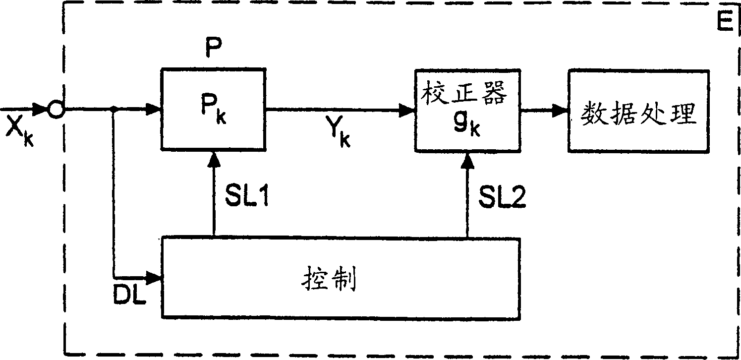
[0061] Receiver E receives received data in a received data packet at step S1. will receive data X k Use packet blocks for transmission. The blocks of data packets are transmitted on time slots of a time division multiple access transmission system, as used in the field of mobile radio.

[0062] Receive data X from the received data X at step S2 k The channel parameters of the transmission channel of the channel H are determined or estimated and stored in the data area of ​​the buffer memory. Among the buffered channel parameters are advantageously the complex channel coefficient h of the impulse response of the transmission channel and the signal-to-noise ratio SNR of the transmission channel H.

[0063] The signal-to-noise ratio SNR is obtained by sending symbols S which are statistically independent k variable σ s 2 and pass the noise signal n k variable σ n 2 The ratio is determined.

[0064] SNR = σ ...


PUM


Abstract

A method for channel equalisation of received data, transmitted via a transmission channel (H), comprises the following steps: receiving (S1) the received data in a received data packet; determining (S2) the channel parameters of the transmission channel (H) from the received data (Xk) and storing the channel parameters in a data field D; calculating (S3) the filter set coefficients (p) of a pre-filter (P) and the equalisation set coefficients (g) of an equaliser by a Givens rotation of the data field (D); setting (S4) the pre-filter (P) and the equaliser with the calculated coefficients (p, g); and equalisation (S5) of the received data by means of the adjusted pre-filter (P) and the adjusted equaliser.

Description

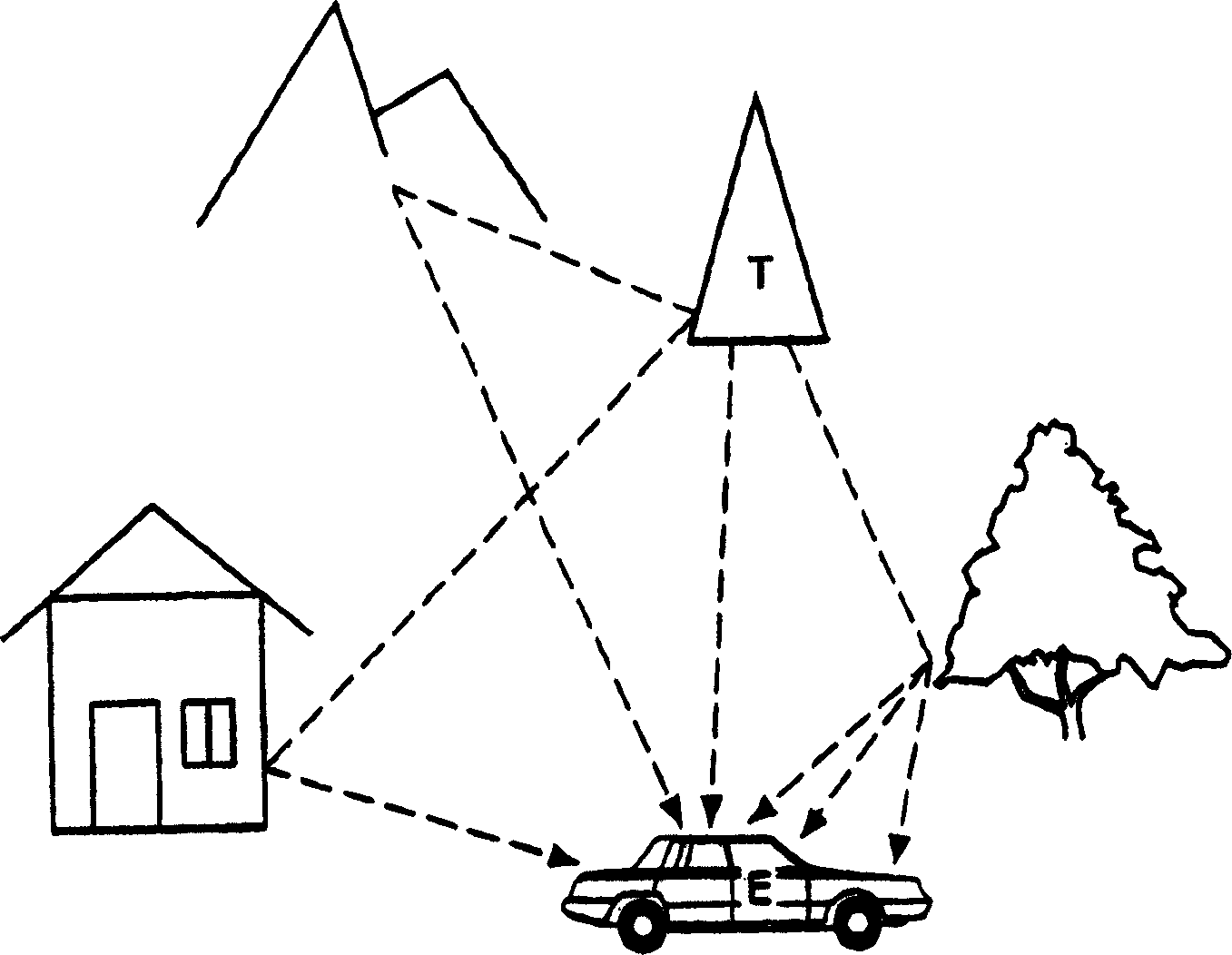
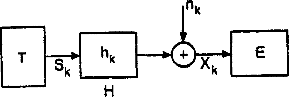
technical field [0001] The invention relates to a channel correction method for received data transmitted via a transmission channel, in which adjustment factors for filters and correctors are determined with low computational complexity and high computational speed. Background technique [0002] A serious problem in communication systems is multipath signal propagation. [0003] attached figure 1 Difficulties in multipath propagation are described. There are generally many possible signal propagation paths between the transmitter or base station T and the mobile station as receiver E. Reflections and scattering of signal waves on buildings, mountains, trees and other obstacles result in a received field strength which is composed of many signal components which generally have different strengths and different delays. [0004] To account for multipath propagation, the transmission channel between a transmitter T and a receiver E can be modeled as having a channel coeffici...

Claims


Application Information

Patent Timeline
Patent Type & Authority Patents(China)
IPC IPC(8): H04B7/005H04B3/06H04L25/03H04L27/00
CPCH04L2025/0349H04L25/03057
Inventor 杨斌P·博恩霍夫
Owner INFINEON TECH AG
Learn More