Radiation testing system and method

A radiation detection and to-be-detected technology, applied in the field of radiation detection systems, can solve problems such as high manufacturing costs

Inactive Publication Date: 2005-04-27
SAMSUNG ELECTRONICS CO LTD
View PDF0 Cites 0 Cited by
  • Summary
  • Abstract
  • Description
  • Claims
  • Application Information

AI Technical Summary

Problems solved by technology

This radiation detection system facilitates instant and accurate photographing of visual images, but it still requires high manufacturing costs

Method used


Image

  • Radiation testing system and method
  • Radiation testing system and method
  • Radiation testing system and method

Examples


Embodiment Construction

[0034] The radiation detection system of the embodiment of the present invention and its usage will be described in detail below with reference to the accompanying drawings.

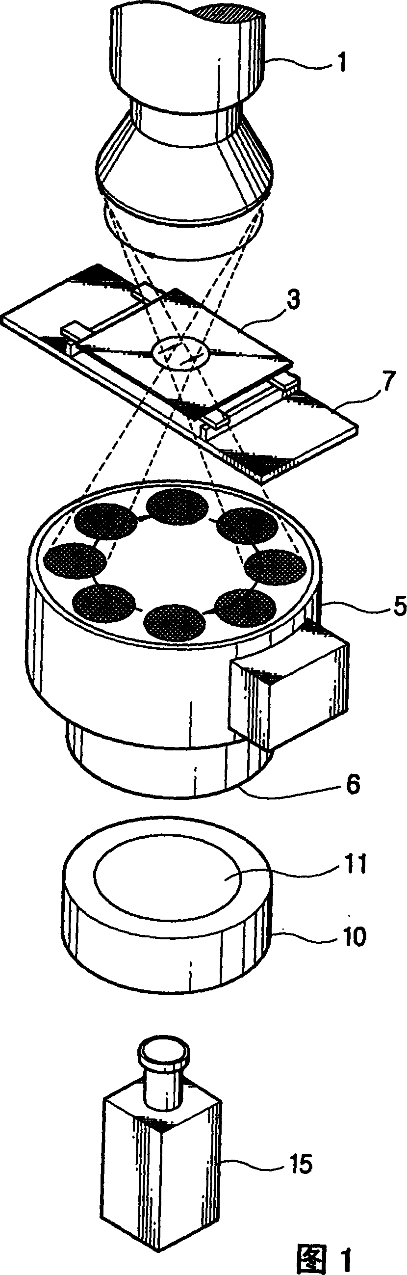
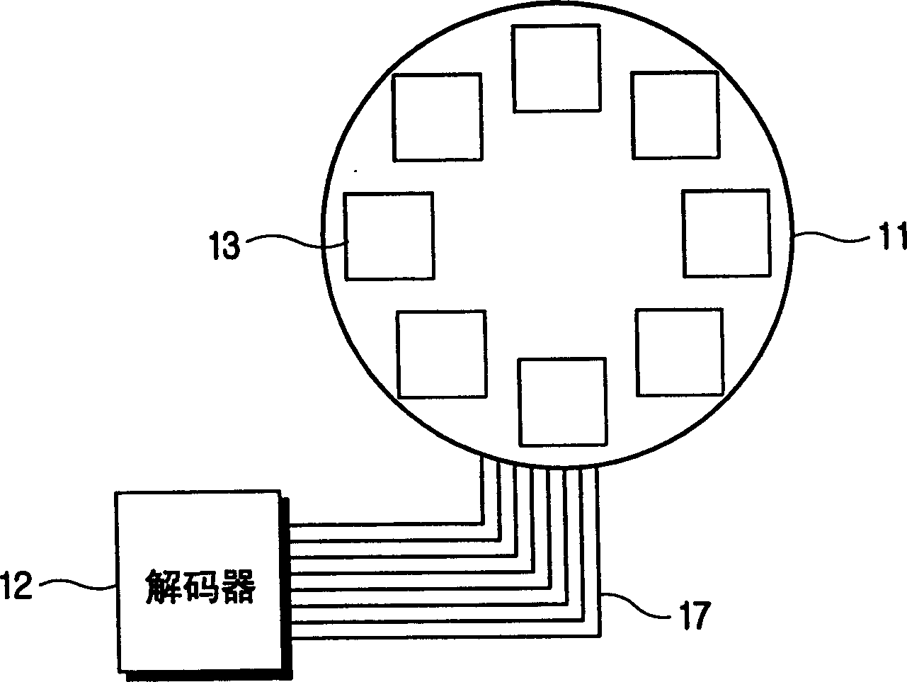
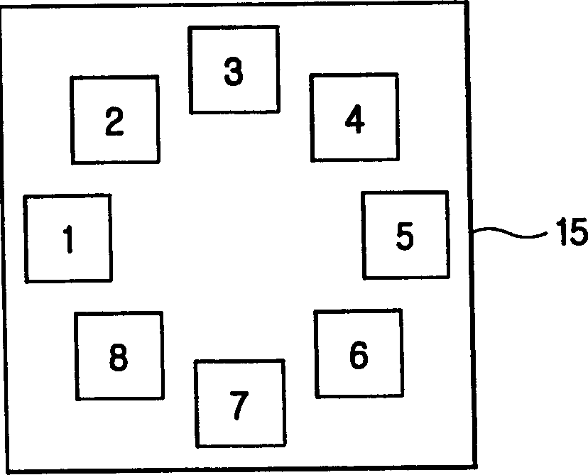
[0035] Fig. 1 schematically represents a perspective view of a radiation detection system of an embodiment of the present invention; figure 2 A top view showing the polarizing filter of the electronic gate shown in Fig. 1. As described therein, the radiation detection system includes: an X-Y table 7 on which an object 3 intended to be detected by NDT is placed; an electron tube 1 for controlling X-rays that produces X-rays to the detection area of ​​the object 3; an image intensifier 5, which is used to form a visual image by the X-rays transmitted through the object 3, it has a visual image part 6, said visual image is projected on it; electronic gate 10, which has a visual image Sending part 11, is used for transmitting the visual image from image intensifier 5 in sequence; And a CCD camera 15, is us...


PUM


Abstract

A radiation inspection system and a method using the same. The system includes a steering radiation electronic tube for generating radiation, and an image intensifier for converting a plurality of projection images formed by projecting the radiation from the steering radiation electronic tube onto an object to be inspected into visual images. The system also includes a visual image part on which the visual images are projected, an electronic shutter having a visual image transmission part for transmitting the visual images from the visual image part of the image intensifier in sequence, and a camera for photographing the visual images from the visual image transmission part of the electronic shutter in sequence. With this configuration, the electronic shutter transmits visual images sequentially.

Description

technical field [0001] The present invention relates generally to radiation detection systems and their use, and more particularly to a radiation detection system and method of use which enable continuous transmission of visual images using electronic gates. Background technique [0002] Radiation includes α-rays, β-rays, γ-rays, X-rays, neutron rays, etc., which cause ionization with matter. X-rays are radio waves with a wavelength of 10-0.001nm, which have optical properties such as radiation and diffraction. Various wavelengths can be precisely measured with diffraction gratings. [0003] X-rays have the ability to see through or pass through objects. The ratio of transmission varies with the material, density and thickness of the object. The X-ray detection method that utilizes the nature of X-rays detects the thickness and position of the blemish in the object from the difference in the photosensitive intensity of the X-ray film. [0004] Diffraction occurs when X-r...

Claims


Application Information

Patent Timeline
IPC IPC(8): G01T1/00G01N23/04G21K1/04G21K5/02G21K5/10H04N5/225
CPCG01N23/04G21K1/04C09J7/20C09J2301/40
Inventor 金榕元朱孝男金亨哲
Owner SAMSUNG ELECTRONICS CO LTD
Why Eureka
Try Eureka