Capacitive microphone device and its connector
A technology of condenser microphone and connecting device, which can be applied to electrical components, sensor protection circuits, electrostatic transducer microphones, etc., and can solve problems such as long wire lengths
- Summary
- Abstract
- Description
- Claims
- Application Information
AI Technical Summary
Problems solved by technology
Method used
Image
Examples
no. 1 example
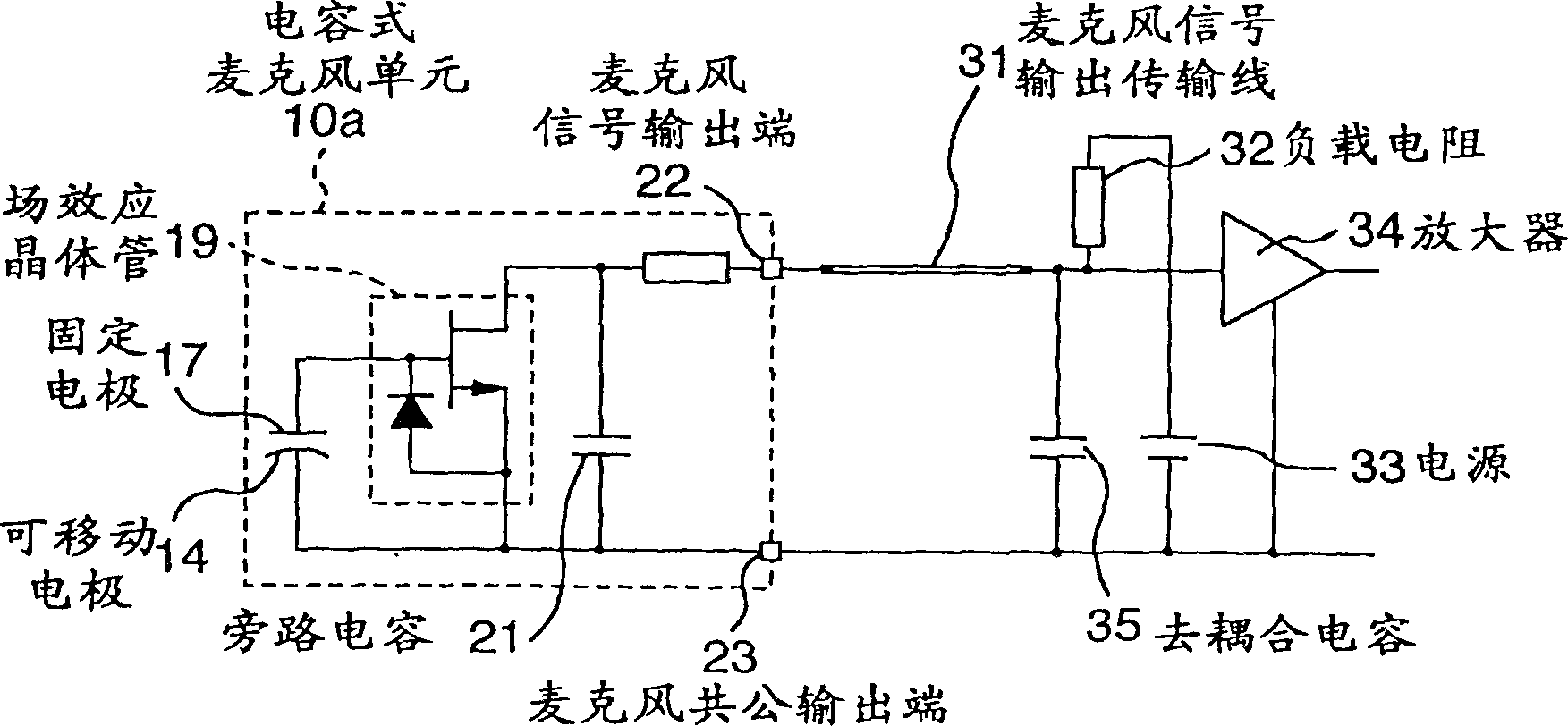
[0051] image 3 Is a circuit diagram of the condenser microphone device in the first embodiment of the present invention; image 3 The difference from the circuit diagram of the conventional condenser microphone device shown in FIG. 2 is that a series resistor 24 is added. image 3 In the condenser microphone unit 10b shown in the figure, the series resistor 24 is inserted between the drain of the field effect transistor 19 and the microphone signal output terminal 22.
[0052] A series resistor 24 is provided to limit the harmonic current, and in the case of a high-frequency equivalent circuit, it is connected in series with the series resonant circuit composed of the microphone signal output transmission line 31 and the bypass capacitor 21. Since the effective series resistance of the bypass capacitor 21 is equal to or less than 1 ohm, the resistance value of the series resistance 24 is selected between tens of ohms to hundreds of ohms, and the resonance current of the micropho...
no. 2 example
[0055] Figure 4 Is a circuit diagram of the condenser microphone device in the second embodiment of the present invention; Figure 4 The difference from the circuit diagram of the conventional condenser microphone device shown in FIG. 2 is that a damping resistor 25 and a blocking capacitor 26 are added. in Figure 4 In the condenser microphone unit 10c shown in, the damping resistor 25 and the blocking capacitor 26 for blocking direct current are connected in series, and the series circuit is connected in parallel with the drain and source of the field effect transistor 19. A damping resistor 25 and a blocking capacitor 26 are provided to dampen the parallel resonance, and are placed in parallel with the parallel resonance circuit composed of the microphone signal output transmission line 31 and the bypass capacitor 21 according to the high-frequency equivalent loop. Since the effective series resistance of the bypass capacitor 21 is equal to or less than 1 ohm, the impedance w...
no. 3 example
[0058]Fig. 5 is a circuit diagram of a conventional condenser microphone unit and the connecting device (connector) in the third embodiment of the present invention. In FIG. 5, the series resistance 27 is included in the connecting device 40a. Both ends of the series resistor 27 are connected to the connector signal input terminal 41 and the connector signal output terminal 43. The microphone signal output terminal 22 and the microphone common output terminal 23 of the condenser microphone unit 10a are connected to the connector signal input terminal 41 and the connector common input terminal 42, respectively. The connector signal output terminal 43 and the connector common output terminal 44 are respectively connected to the microphone signal output terminal transmission line 31 and the common terminal (ground) on the motherboard of a cellular phone or similar device, and constitute a condenser microphone device, and a load The resistor, the power source 33 and the amplifier 34 w...
PUM
 Abstract
Description
Claims
Application Information
 - R&D
- Intellectual Property
- Life Sciences
- Materials
- Tech Scout
- Unparalleled Data Quality
- Higher Quality Content
- 60% Fewer Hallucinations
Browse by: Latest US Patents, China's latest patents, Technical Efficacy Thesaurus, Application Domain, Technology Topic, Popular Technical Reports.
© 2025 PatSnap. All rights reserved.Legal|Privacy policy|Modern Slavery Act Transparency Statement|Sitemap|About US| Contact US: help@patsnap.com


