
Marker lamp system

A sign light and lighting technology, which is applied in the field of sign light systems, can solve the problem that it is difficult for light-emitting diodes to achieve the wide light distribution characteristics of sign lights, and achieve the effects of improving lamp efficiency, saving energy, and reducing inclination angles

Inactive Publication Date: 2005-04-13
TOSHIBA LIGHTING & TECH CORP
View PDF0 Cites 0 Cited by
  • Summary
  • Abstract
  • Description
  • Claims
  • Application Information

AI Technical Summary

Problems solved by technology

Therefore, it is difficult to achieve the wide light distribution characteristics required by the sign lights with the fewest number of light-emitting diodes.

Method used


Image

  • Marker lamp system
  • Marker lamp system
  • Marker lamp system

Examples


Embodiment Construction

[0172] Embodiments of the present invention will be described in detail below with reference to the drawings. First, the marker light system of the present invention will be described.

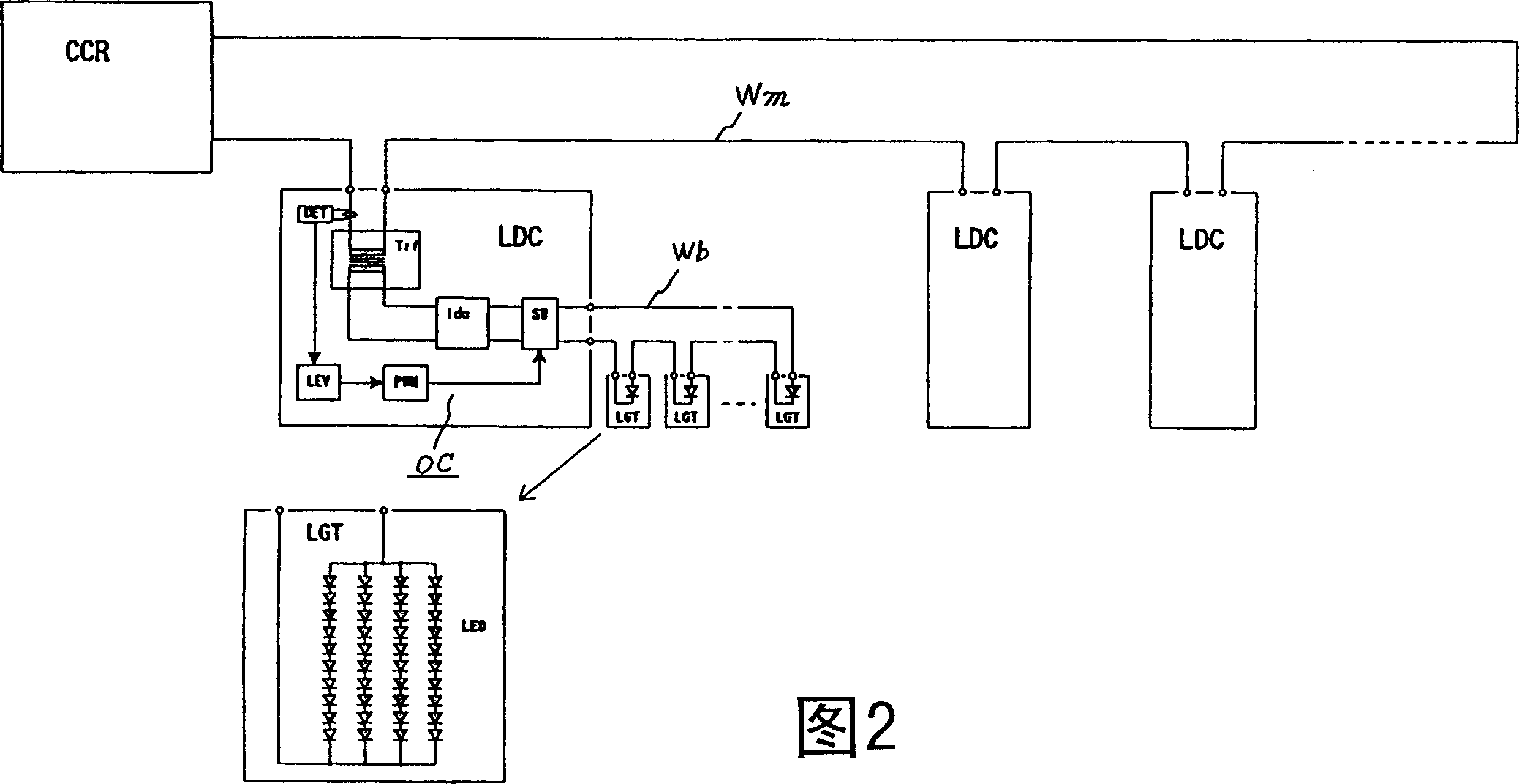
[0173] Fig. 2 is a circuit diagram showing an aviation marking light system for airports as a first embodiment of the marking light system of the present invention.

[0174] In the figure, CCR is an AC constant current power supply, Wm is a series connection trunk cable, LDC is a control circuit, Wb is a branch line cable, and LGT is an aviation marker light.

[0175]

[0176] The AC constant-current power supply CCR is an AC constant-current power supply for a sign lamp using an existing halogen lamp, and it has a current switching tap.

[0177]

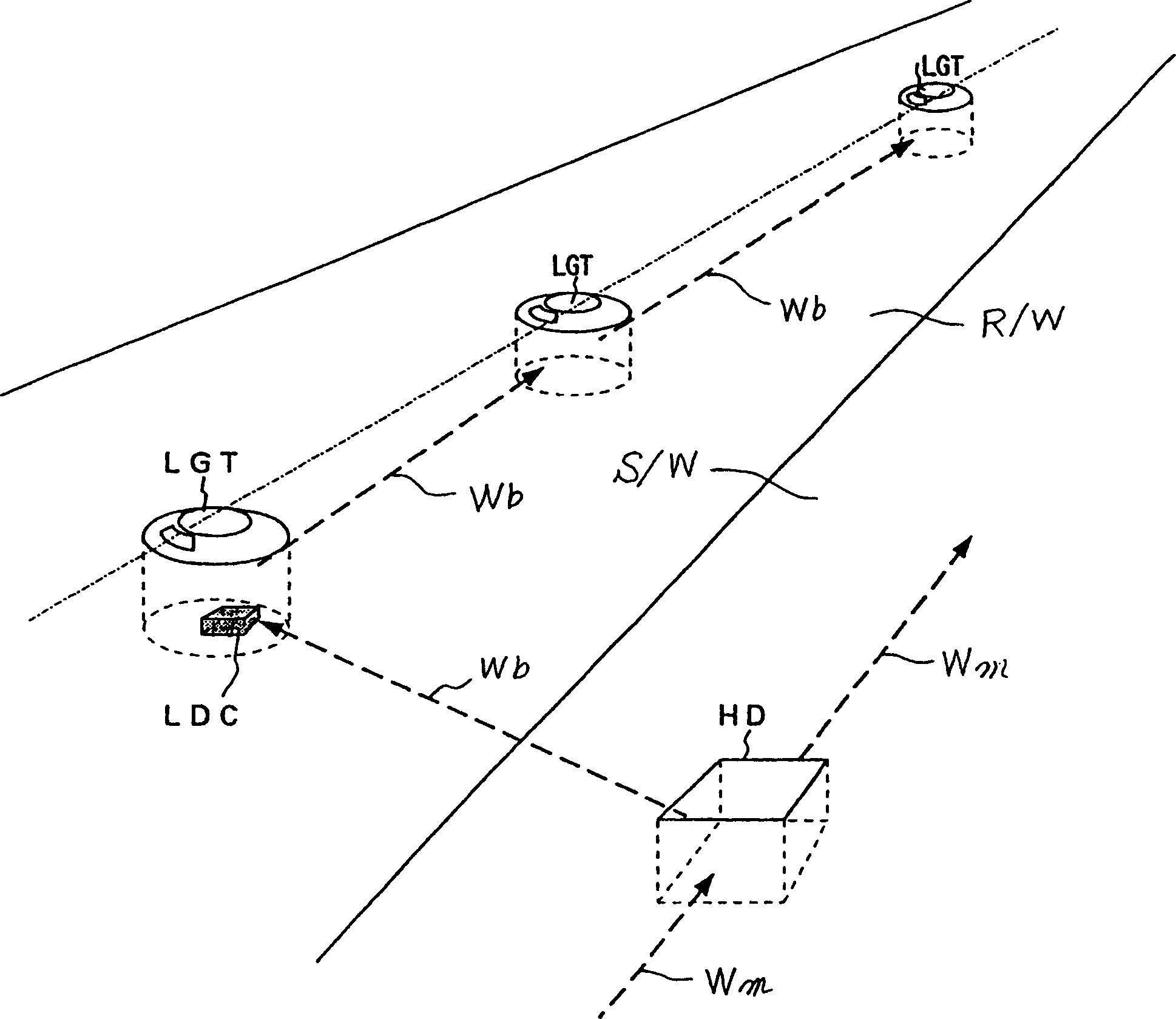
[0178] The trunk cable Wm is connected in series, and its laying position is along the runway and the roadside where the aviation marker light LGT is installed.

[0179]

[0180] The control circuit LDC is composed of a plurality of discrete...


PUM


Abstract

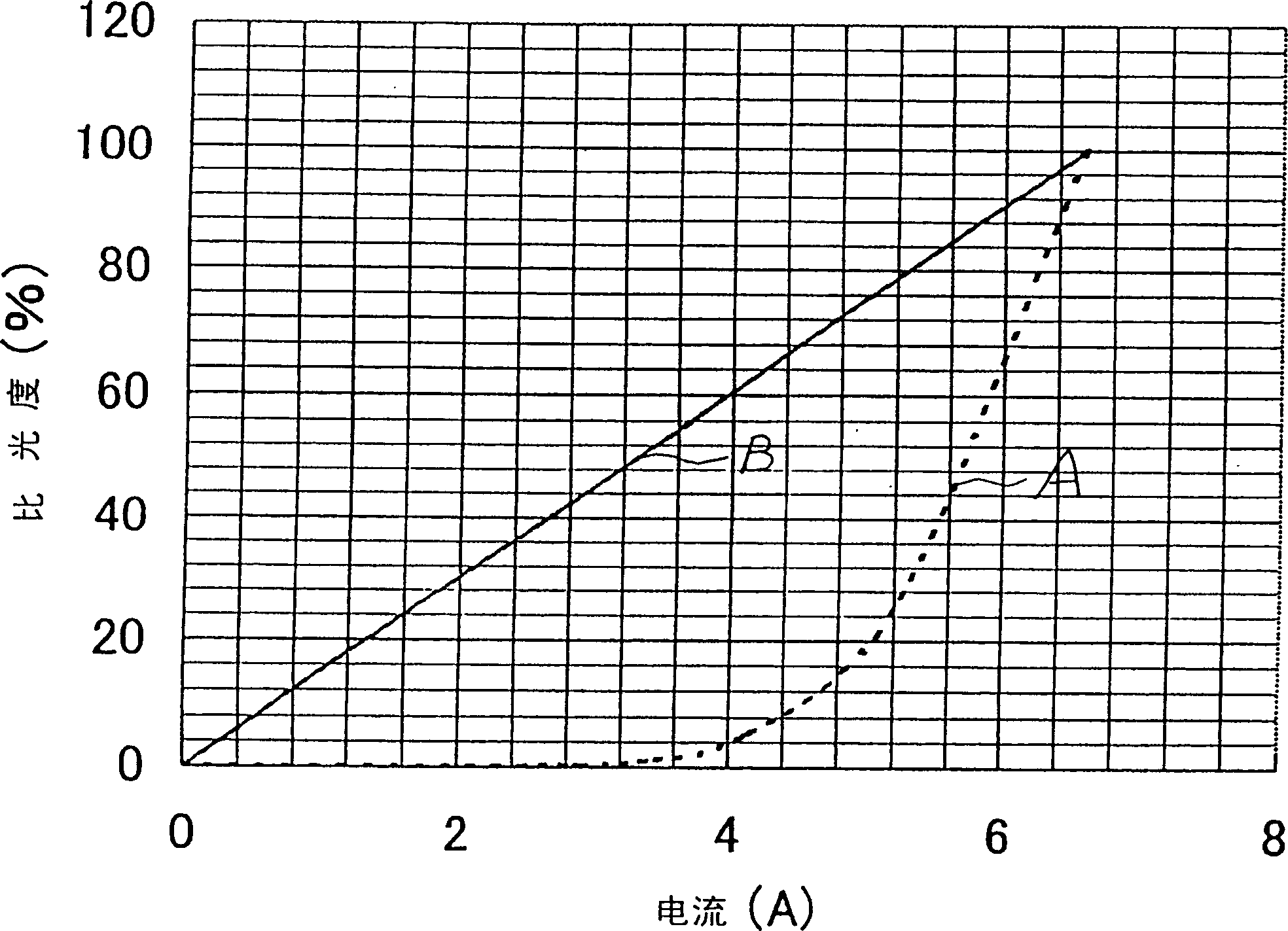
The present invention provides a marker lamp system, even though the AC constant current power supply performs current switching according to the characteristics different from the current-photometric characteristic of light-emitting diodes, the marker lamp brightness can still be switched according to the specified photometric ratio. It has: AC constant current power supply CCR, sign lamp LGT using light-emitting diode LED as power supply, current detection device DET for detecting the output current of AC constant current power supply, and lighting control device OC for controlling sign lamp LGT to a predetermined luminosity ratio. The invention also provides a marker lamp. It has a marker lamp main body M equipped with a light-emitting window (2b) and a light-emitting diode unit LU, which has a plurality of light-emitting diodes (3) arranged side by side. The outer shape of the lens portion (3a) is horizontally long when viewed from the axial direction, and the axial light distribution characteristic curve is horizontally long, so that the combined light distribution can be widened.

Description

technical field [0001] The present invention relates to a marker light system used in airports and the like, and relates to a marker light suitable for the marker light system, in particular to a marker light suitable for a buried marker light. Background technique [0002] The sign lights used in airports and other places are connected to the output end of the AC constant current power supply in series to obtain electrical energy. In addition, in order to maintain good visibility even when the surrounding brightness changes, the method of switching the output current of the AC constant current power supply according to the surrounding brightness is used for control, so that the marker light works according to the specified luminosity ratio. For example, set the switching tap of the output current on the AC constant current power supply so that the photometric ratio can be selected as 100%, 25%, 5%, 1%. [0003] In addition, the light source of the sign lamp currently used ...

Claims


Application Information

Patent Timeline
Patent Type & Authority Patents(China)
IPC IPC(8): E01C17/00F21K9/23F21V5/04F21Y115/10
Inventor 井手胜幸芝田和明石田康史泉贤晴长谷川润治新野真吾
Owner TOSHIBA LIGHTING & TECH CORP
Learn More