Coiling controlling method

A control method and winding shaft technology, applied in the direction of winding strips, control systems, shearing machine control devices, etc., to achieve the effect of reducing costs and reducing the size of the machine

Inactive Publication Date: 2005-02-16
FUJI IRON WORKS CO LTD
View PDF0 Cites 0 Cited by
  • Summary
  • Abstract
  • Description
  • Claims
  • Application Information

AI Technical Summary

Problems solved by technology

[0005] However, in the above-mentioned conventional method, since the lead-out roller of the lead-out part must tension the thin metal strip of the uncoiling part with an appropriate tension force, the frictional force between the thin metal strip and the surface of the lead-out roller and the amount of engagement between the lead-out roller and the thin metal strip must be provided. , the number of leading rollers and other important conditions, and involves complicated factors
[0006] In addition, although the pull-out part is tensioned with the tension necessary to wind the thin metal strip from the winding part, a pull-out device that prevents the thin metal strip from being deflected under this tension is required.

Method used


Image

  • Coiling controlling method
  • Coiling controlling method
  • Coiling controlling method

Examples


Embodiment Construction

[0016] Hereinafter, specific embodiments of the present invention will be described with reference to the drawings.

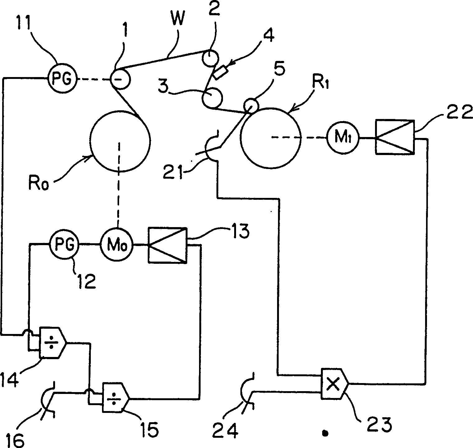
[0017] figure 1 Shows the winding control of a representative slitting shear as an outline of the drive system for winding control of the present invention. In the figure, Ro is an unwinding roller, and R 1 In order to wind the rollers, the wide metal thin strip W is drawn out from the unwinding roller Ro installed on the winding shaft through the lead-out roller 1, and is cut into multiple pieces in the length direction with the slitting scissors blade 4 between the guide rollers 2, 3 A narrow metal thin strip, the cut narrow metal thin strip is alternately separated up and down or front and back, and the roller 5 is brought into contact with the respective up and down or front and rear winding shafts to serve as the winding roller R 1 Winding is almost the same as the conventional slitting shear device.

[0018] However, the driving system of the present inventi...


PUM


Abstract

The invention reduces a size of a machine and costs greatly by shortening length between an unwinding shaft and a winding shaft of a slitter or the like. When a web is unwound from the unwinding shaft and is rewound to the winding shaft as it is or when the web is cut in a plurality of strips of webs in a longitudinal direction, is separated in up and down directions or back and forth directions alternately, and is wound to upper and lower or back and front winding shafts, the unwinding shaft is driven and pays out at a set speed of the web, and the winding shaft is driven and winds with a set tensile force of the web. Guide rollers 2, 3 for guiding the web are provided between the unwinding shaft and the winding shaft, and the guide rollers 2, 3 rotates together by contacting with the web W without active driving.

Description

Technical field [0001] The present invention relates to a winding control method when a thin metal strip is drawn out from an unwinding shaft and wound on a winding shaft, and specifically relates to a longitudinal method of cutting and separating a wide metal thin strip into a plurality of narrow metal thin strips to be wound. Winding control method of cutting and shearing machine. Background technique [0002] As a device for winding a thin metal strip drawn from an unwinding shaft on a winding shaft, it has been known and widely used in the past to cut a wide metal thin strip into a plurality of narrow metal thin strips along its length direction. The slitting shear device in which the cut narrow metal thin strips are alternately separated up and down or back and forth and wound on the respective up and down or front and back winding shafts, such as figure 2 As shown, the winding control device of this slitting shear is generally provided with a brake 31 on the unwinding shaf...

Claims


Application Information

Patent Timeline
Patent Type & Authority Patents(China)
IPC IPC(8): B65H18/14B65H23/18B65H23/198B65H35/02B65H77/00
CPCB65H2301/4148B65H18/103B65H2513/11B65H23/1806B65H2515/31B65H35/02B65H2220/03
Inventor 上山实石田敏也
Owner FUJI IRON WORKS CO LTD
Why Eureka
Try Eureka