
Circuit for harmonizing read and wright between central processor and input output interface device

A central processing unit, input and output technology, applied in electrical digital data processing, instruments, etc., can solve problems such as slow speed, data transmission errors, and inability to confirm in time, so as to reduce system design problems and avoid transmission errors.

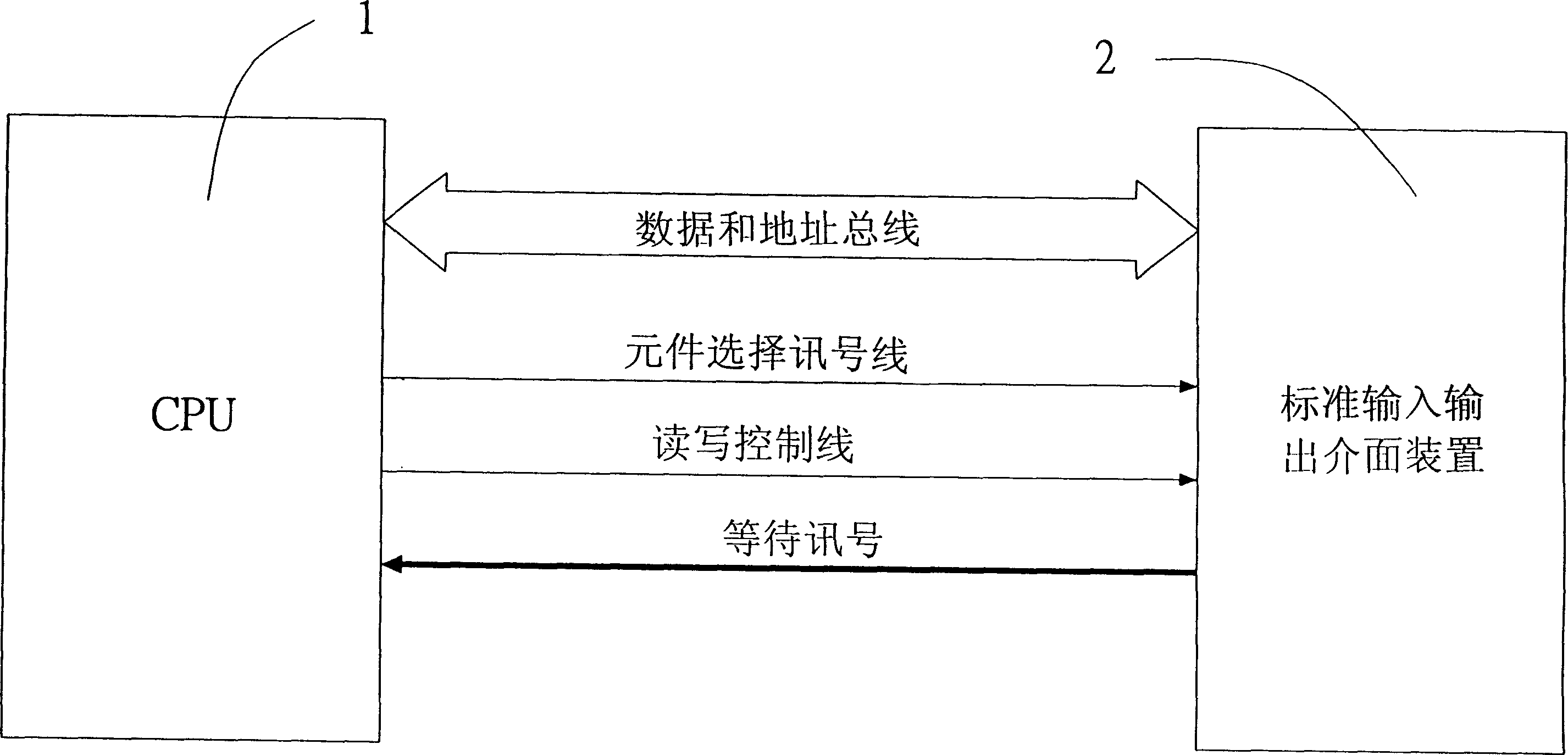
Inactive Publication Date: 2005-01-19
CAMEO COMM
View PDF0 Cites 0 Cited by
  • Summary
  • Abstract
  • Description
  • Claims
  • Application Information

AI Technical Summary

Problems solved by technology

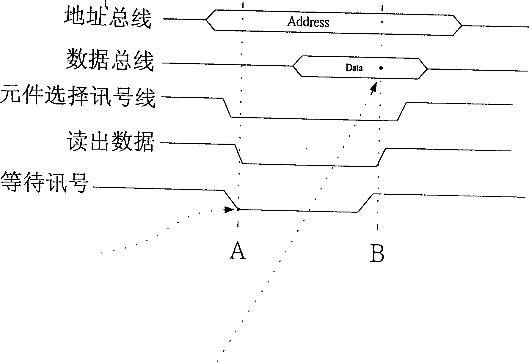
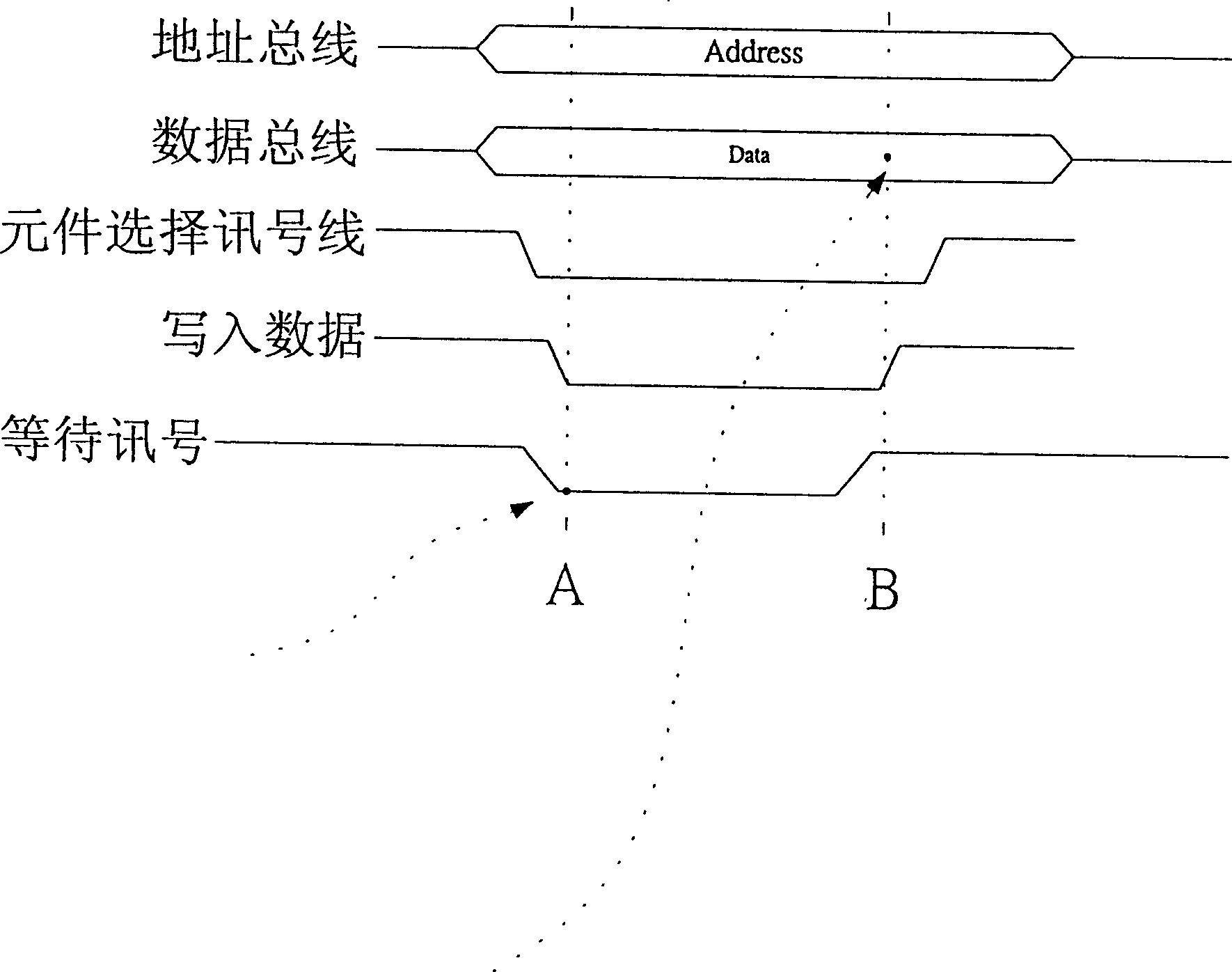
[0004] However, the PCMCIA Card (Standard Input Output Interface Device) 2 of general computer peripheral equipment is not as fast as the CPU (Central Processing Unit) 1 in execution speed. The speed has been greatly increased from the early 4MHZ and 8MHZ to the high-speed timing pulse (Clock) of hundreds of MHZ or even GHZ today. Therefore, when the high-speed CPU (central processing unit) 1 is connected to the low-speed PCMCIA Card (standard input and output interface device) ) 2 When requesting to read or write (READ / WRITE) data (see Figures 4 and 5 again), it is often easy to issue WAIT ( Waiting for signal) signal informs CPU (central processing unit) 1 that it is currently in an unready state (READ / WRITE or DATA has no signal coming in) and thus causes CPU (central processing unit) 1 to read or write at present The data are all incorrect data. The main reason is that the CPU (central processing unit) 1 cannot detect the waiting signal (taking the low potential trigger as an example) on the detection starting point A of the effective timing pulse, so that the detection cut-off point B cannot confirm in time whether it is necessary to continue sending WAIT (wait signal) requests, and directly executes the reading or writing action, resulting in data transmission errors. Therefore, for high-speed CPU (central processing unit) 1 and lower speed The synchronization (Synchronization) or processing (Handshaking) between the computer peripheral equipment, sometimes need to use cumbersome software calculations to control and eliminate the error between the speeds, and sometimes need to reduce the overall working timing of the system, but it will cause the overall system to work Poor efficiency and increased trouble in system design

Method used


Image

  • Circuit for harmonizing read and wright between central processor and input output interface device
  • Circuit for harmonizing read and wright between central processor and input output interface device
  • Circuit for harmonizing read and wright between central processor and input output interface device

Examples


Embodiment Construction

[0032] see Image 6 Shown, the present invention is to set up a synchronous control unit 3 and a signal input unit 5 between CPU (central processing unit) 1 and PCMCIA Card (standard input and output interface device) 2 with reference to shown in Fig. 7,8, wherein this synchronous control Unit 3 may include:

[0033] An inverter 31, the input terminal is connected to the output terminal of a read-write signal extractor 32, and the reverse output terminal is connected to one input terminal of the first comparison logic gate 33, and is controlled by the trigger terminal When the connected CPU (Central Processing Unit) 1 is input with timing pulse (Clock) 4, the reverse output terminal can provide a reverse sync pulse status.

[0034] A read-write signal picker 32, the input end is respectively connected with the signal control lines of the read end (READ) and the write end (WRITE), and the output end is connected to the input end of an inverter 31, when When one of the read te...


PUM


Abstract

A circuit for coordinating the R / W operation between CPU and I / O interface is a synchronization controller connected between them. When a R / W request is sent from CPU to I / O interface and the I / O interface is not ready, its sents a synchronous wait compensating signal to CPU to make it in waist state until the I / O interface is ready. Then R / W operation is conducted.

Description

technical field [0001] The invention relates to a calculator circuit, in particular to a circuit for coordinating reading and writing between a central processing unit and an input and output interface device. Background technique [0002] figure 1 What is shown is an example of data transmission between a general CPU (central processing unit) 1 and a PCMCIA Card (standard input and output interface device). [0003] Wherein when the CPU (central processing unit) 1 performs data transmission to the peripheral equipment, the PCMCIA Card (standard input and output interface device) addresses and assembles the data through the DATA BUS (data bus) and ADDRESS BUS (address bus), and Use the Chip Select (component selection signal line), READ / WRITE (reading and writing control line) and WAIT (waiting signal) lines of the CONTROL BUS (control bus) to control the direction of data transmission and whether to open or not. When ready, first send a wait signal to the CPU (central pro...

Claims


Application Information

Patent Timeline
Patent Type & Authority Patents(China)
IPC IPC(8): G06F13/42
Inventor 吴铭修
Owner CAMEO COMM
Learn More