Method and apparatus for galvanically isolating two integrated circuits from each others

An integrated circuit, DC isolation technology, applied in the direction of circuit, logic circuit connection/interface layout, logic circuit coupling/interface for bidirectional operation, etc., to achieve the effect of reducing area

Inactive Publication Date: 2005-01-05
TEXAS INSTR INC
View PDF0 Cites 0 Cited by
  • Summary
  • Abstract
  • Description
  • Claims
  • Application Information

AI Technical Summary

Problems solved by technology

[0012] Another point considered in the device design of the interface circuit constructed according to the IEEE 1394-1995 standard is the propagation delay through the interface circuit

Method used


Image

  • Method and apparatus for galvanically isolating two integrated circuits from each others
  • Method and apparatus for galvanically isolating two integrated circuits from each others
  • Method and apparatus for galvanically isolating two integrated circuits from each others

Examples


Embodiment Construction

[0033] It should be noted that the process steps and structures described here are not necessary to form a complete process flow for fabricating integrated circuits. It is contemplated that the present invention may be practiced in conjunction with integrated circuit fabrication techniques currently used in the art, and only the inclusion of such conventional process steps is necessary for an understanding of the present invention.

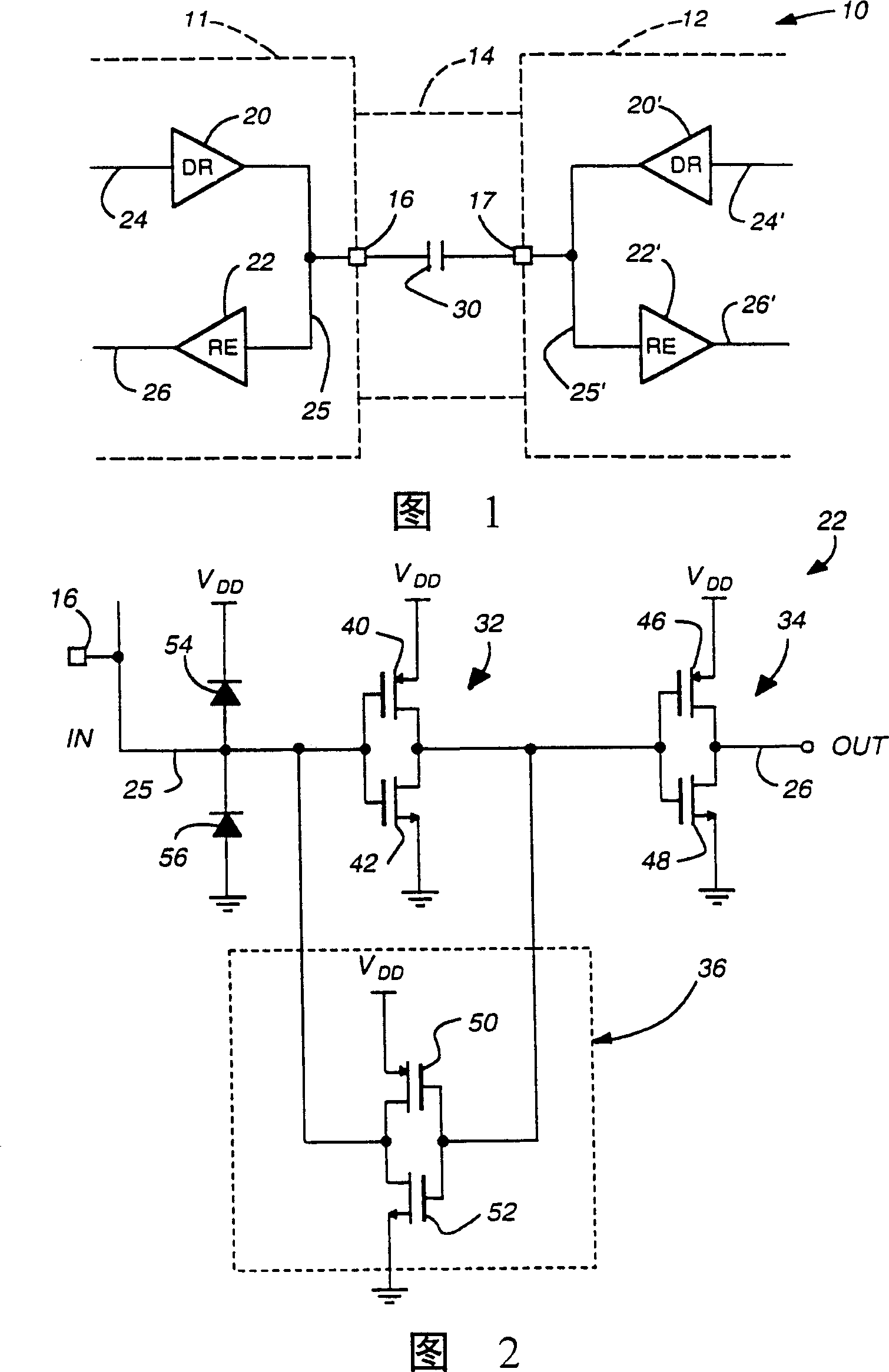
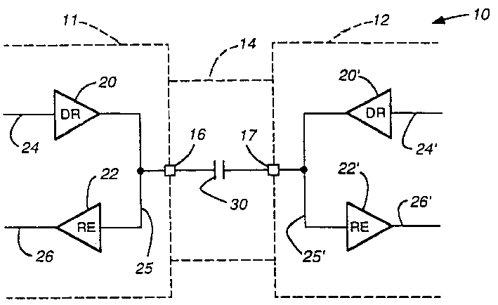
[0034] The improved solution of the present invention is to use a lock input and a standard CMOS output connected by a capacitor, which acts as an isolation barrier. Since the charge on the capacitor cannot change instantaneously, a CMOS output on one side of the isolation barrier raises or lowers the corresponding input on the other side of the isolation barrier. At this point, the latch input holds the charge on the capacitor until the output changes in the other direction.

[0035] It will become apparent that, compared to prior art swings of ...


PUM


Abstract

An isolation circuit (10) and method for providing dc isolation between two integrated circuit devices (11) and (12) that may be referenced to different ground potentials is presented. The isolation circuit includes, in each circuit, an output buffer (20, 20') connected to deliver a signal to an input / output pin (16, 17) of the circuit (11, 12) with which the output buffer is associated. A capacitance (30), which may be a single capacitor or a combination of capacitors, is connected to the pins (16, 17) of each of the circuits, and in each circuit, an input buffer (22, 22') is connected to receive a signal delivered onto the I / O pin. A transformer is used to provide dc isolation between the two integrated circuits.

Description

technical field [0001] This invention relates to improvements in integrated circuit isolation techniques and devices, and more particularly to improvements in devices and methods for isolating two circuits, such as integrated circuits or the like, from each other on direct current. Background technique [0002] In many circuit configurations, it is often necessary to provide DC isolation between two or more integrated circuits. For example, the ground potential of one integrated circuit may normally be at a different DC level than the ground potential of another integrated circuit to which it is connected. When such separation of ground potential is required, various general ground isolation schemes are available. For example, one approach is that described in Annex J in Institute of Electrical and Electronics Engineers (IEEE) 1394-1995. [0003] However, in the past, when isolated ground design circuits such as those described in IEEE 1394-1995 were required, the physical...

Claims


Application Information

Patent Timeline
IPC IPC(8): H03K19/0175H04L25/02
CPCH01L2924/0002H03K19/01759H01L2924/00H03K19/0016
Inventor D·A·亚克林K·L·科恩荷
Owner TEXAS INSTR INC
Why Eureka
Try Eureka