
Oil slurry charring firing device and its method

A slurry and carbonization technology, which is applied in the petroleum industry, coking carbonaceous materials, coking ovens, etc., can solve problems such as long analysis time, unfavorable catalyst powder research, and large solvent consumption

Inactive Publication Date: 2004-09-15
CHINA PETROLEUM & CHEM CORP +1
View PDF0 Cites 0 Cited by
  • Summary
  • Abstract
  • Description
  • Claims
  • Application Information

AI Technical Summary

Problems solved by technology

[0004] In addition, there are other similar methods that are used for reference in the measurement of the solid content of oil slurry, such as "GB / T508-91 Determination of Ash Content in Petroleum Products (Gravimetric Method)", which has a cumbersome operation process, long analysis time, and The operating temperature of 800 °C used will damage the microstructure of the catalyst to a certain extent, which is not conducive to the further study of the formation mechanism of the catalyst powder; "GB / T511-88 Determination of mechanical impurities in petroleum products and additives (gravimetric method)", This method consumes a large amount of solvent, the operation process is cumbersome, and the analysis time is long. The main reason is that the coke on the surface of the catalyst cannot be completely washed off by the organic solvent, and the result does not fully represent the content of the catalyst powder in the oil slurry.
[0005] From above-mentioned prior art, because do not have suitable treatment oil slurry charring burning device, make the mensuration of solid content in oil slurry not accurate enough at present, and because the destruction of catalyst microstructure, can't make the formation mechanism of catalyst powder further research

Method used


Image

  • Oil slurry charring firing device and its method
  • Oil slurry charring firing device and its method
  • Oil slurry charring firing device and its method

Examples


Embodiment Construction

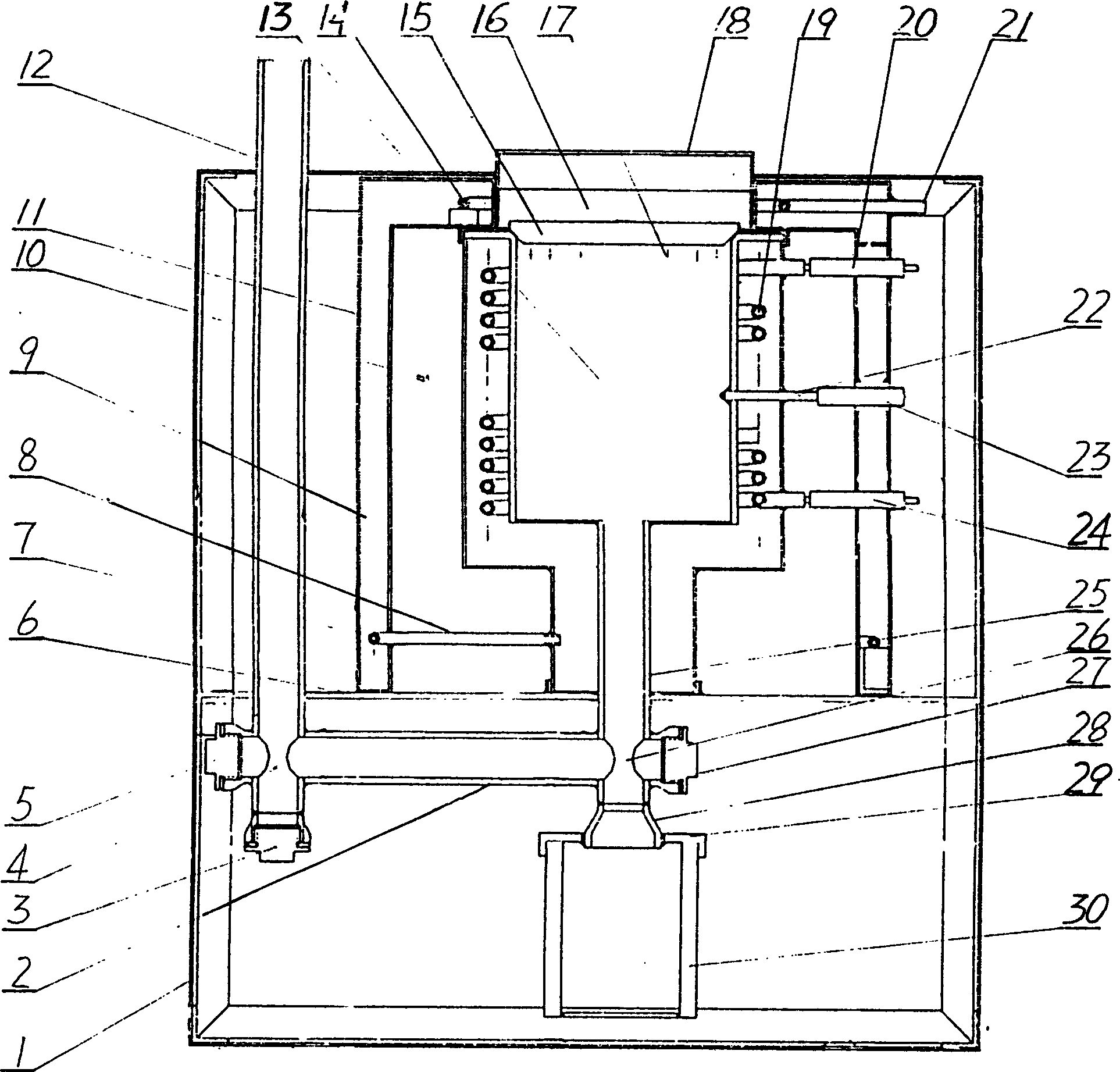
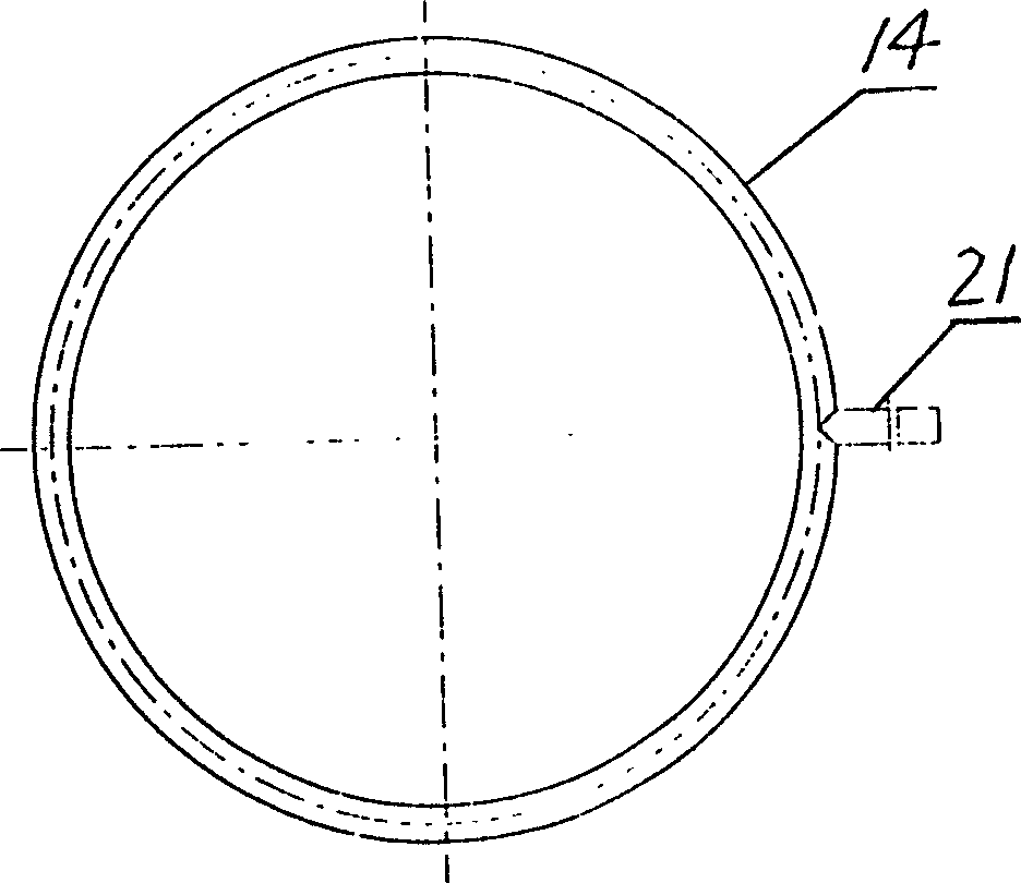
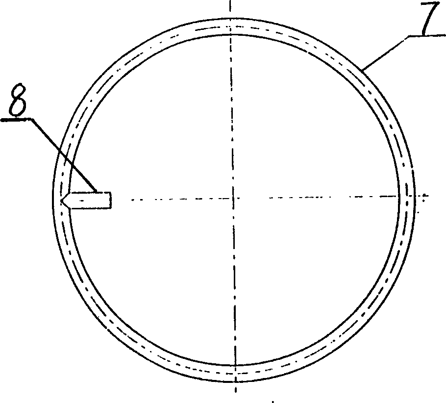
[0012] First look figure 1 , The oil slurry carbonization burning device consists of the chassis 1, the flue pipe 2, 12, 25, the flue plug 3, 5, 27, the cross 4, 26, the partition 6, the gas outlet ring pipe 7, the gas outlet pipe 8, Insulation jacket 9, thermal insulation layer 10, 16, heating jacket 11, sample box 13, air inlet ring tube 14, top plug 15, air outlet 17, top cover 18, heating tube 19, heating tube connector 20, 24, inlet The gas connector 21, the thermocouple 22, the thermocouple connector 23, the cone section tube 28, the cup cap 29, and the cup 30 are composed.

[0013] In the oil slurry carbonization and burning device of the present invention, the chassis 1 can be made of a square frame welded by angle iron and then covered with white iron. It is divided into upper and lower parts by a partition 6. The upper part separated by the partition 6 is mainly a heating furnace. The insulation jacket 9 and the heating jacket 11 are both cylindrical in shape. The insul...


PUM


Abstract

An oil slurry burning apparatus for carbonizing it is composed of machine casing, partition, insulating jacket, gas inlet and outlet tubes, insulating layer, heating jacket, heating tube, specimen box, top cover and connecting pipes. Its advantages are no need of solvent, simple operation, and no damage to microscopic structure of catalyst.

Description

Technical field [0001] The invention relates to an oil slurry carbonization burning device and a method of use. Background technique [0002] The oil slurry of the catalytic cracking process contains catalyst powder and trace ash. The content of the catalyst powder in the oil slurry is related to the strength of the catalyst and the separation efficiency of the cyclone separator. With the continuous improvement of petrochemical refining technology, the solid content in the oil slurry, that is, the catalyst powder, has been significantly reduced; at the same time, with the continuous expansion of the use of the oil slurry, the requirements for the solid content of the oil slurry have become more and more stringent. The analysis and determination of pulp solid content also put forward higher requirements. [0003] At present, the commonly used method for determining the solid content of oil slurry is the solvent dilution centrifugal method. This method has a large human error and i...

Claims


Application Information

Patent Timeline
Patent Type & Authority Patents(China)
IPC IPC(8): C10B55/00
Inventor 范登利蔺玉贵
Owner CHINA PETROLEUM & CHEM CORP
Learn More