
Pseudospherical collimation microlens for optic fibre collimator

A technology of optical fiber collimator and spherical collimation, which is applied in the direction of lens, optical waveguide coupling, instrument, etc., can solve the problems of optical signal loss, insertion loss increase, etc., achieve long working distance, eliminate aberration, and low cost Effect

Inactive Publication Date: 2004-09-01
ZHEJIANG UNIV
View PDF0 Cites 0 Cited by
  • Summary
  • Abstract
  • Description
  • Claims
  • Application Information

AI Technical Summary

Problems solved by technology

However, due to the unavoidable optical aberration in the imaging of a single spherical surface, the beam collimated and focused by the spherical microlens cannot be completely coupled into the receiving fiber without loss, which causes the loss of optical signals, that is, the increase of insertion loss. Big

Method used


Image

  • Pseudospherical collimation microlens for optic fibre collimator
  • Pseudospherical collimation microlens for optic fibre collimator
  • Pseudospherical collimation microlens for optic fibre collimator

Examples


Embodiment Construction

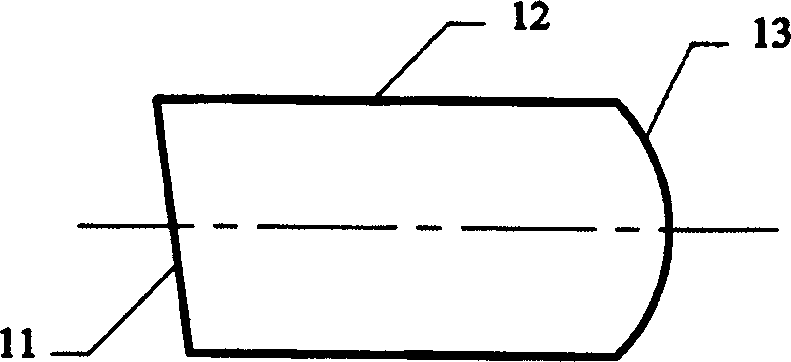
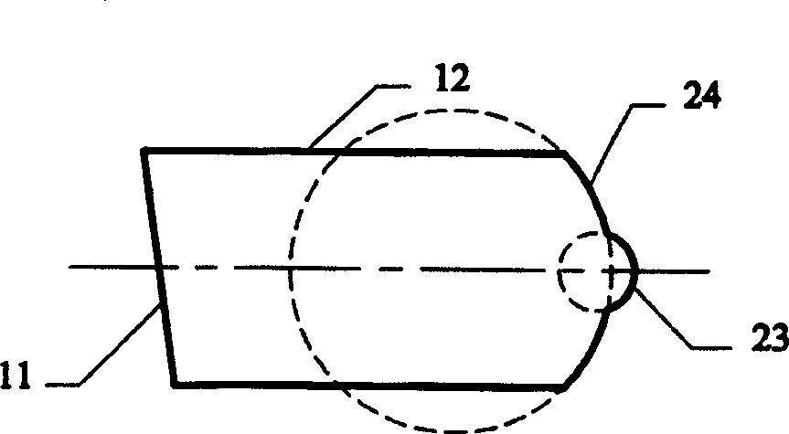
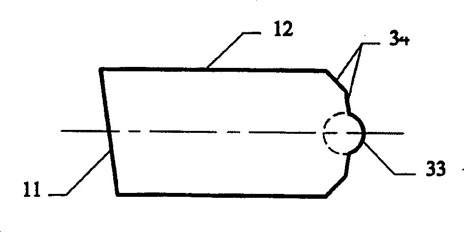
[0014] The above pseudospherical collimating microlens used in the fiber collimator has a pseudospherical end surface with a vertical axis, a cylindrical side surface and another inclined end surface. The lens material is a homogeneous refractive index optical material. The pseudospherical vertical axis end surface is formed by a combination of coaxial spherical surfaces 23 and 24 with different curvatures or conical surfaces 33 and 34 with different inclination angles, and is perpendicular to the main axis of the pseudospherical collimating microlens used in the fiber collimator. The surface shape of the inclined end surface is a plane, and its normal line forms an included angle of 6∽12° with the main axis of the pseudospherical collimating microlens used for the fiber collimator. Pseudo-spherical vertical axis end face and inclined end face are coated with anti-reflection coating.

[0015] The processing of the pseudo-spherical collimating microlens used in the fiber colli...


PUM


Abstract

The invention discloses a fake-sphere collimation micro-lens which applies to optical fibre collimator. It has fake-sphere droopy-axis end face, column side face and another declining end face. Advantage of the invention is: the fake-sphere droopy end face which uses in fake-sphere collimator micro-lens of optical fibre collimator as mentioned above is made up of several sections of coaxial sphere with various curvature or cone-type face with various obliquity, its profile of surface is close to particular non-spherical surface in order to eliminate aberration engendered by sphere lens as fully as possible and make insert loss reduce to the level approximate to non-spherical micro-lens. At the same time, above mentioned fake-sphere droopy-axis end face is easy to process and its cost is close to cheap sphere collimation lens.

Description

technical field [0001] The invention relates to an optical element used in optical fiber communication, in particular to an important component in an optical fiber collimator: a pseudospherical collimating microlens used in the optical fiber collimator. Background technique [0002] Fiber collimators are widely used in optical communication passive devices as independent components: a collimator can convert the divergent beam emitted by the source fiber into a parallel beam, so that various passive devices such as isolators, circulators, optical switches After the optical signal is effectively processed, another collimator is used to converge the processed beam onto the receiving optical fiber, so that the optical signal is coupled into the receiving optical fiber without loss and continues to transmit. like Figure 4 As shown, a conventional typical fiber collimator is made by fixing an optical fiber head 41 and a collimating lens 42 through a conn...

Claims


Application Information

Patent Timeline
Patent Type & Authority Patents(China)
IPC IPC(8): G02B3/02G02B6/32
Inventor 张全薛可云
Owner ZHEJIANG UNIV
Learn More