
Ship anchor type anchor head of ground anchor stretching when grouting

A technology of grouting and ship anchoring, which is applied in the direction of earthwork drilling, installation of anchor rods, sheet pile walls, etc., which can solve the problems of limited depth, limited supply of anchoring force, complicated construction technology, etc., and achieve large anchoring force and convenient construction Effect

Inactive Publication Date: 2004-08-18
SHANGHAI JIAO TONG UNIV
View PDF0 Cites 6 Cited by
  • Summary
  • Abstract
  • Description
  • Claims
  • Application Information

AI Technical Summary

Problems solved by technology

However, these methods and the anchoring end structures formed have their disadvantages: special reaming equipment or materials are required, the construction process is complex, large-volume reaming is very difficult, and the supply of anchoring force is limited.
However, the depth of the ribs embedded in the soil is limited, and the pullout force provided is difficult to improve greatly (especially in softer soil layers). Moreover, this method needs to be advanced with a repetitive jack and applies a reverse pull force, which also brings disadvantages to construction applications. to limit

Method used


Image

  • Ship anchor type anchor head of ground anchor stretching when grouting
  • Ship anchor type anchor head of ground anchor stretching when grouting
  • Ship anchor type anchor head of ground anchor stretching when grouting

Examples


Embodiment Construction

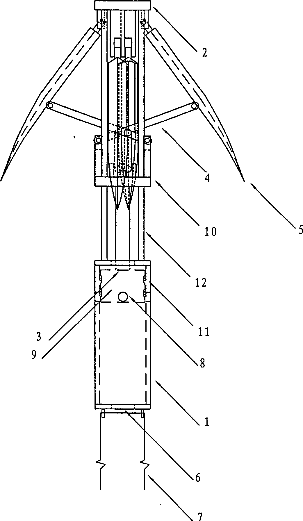
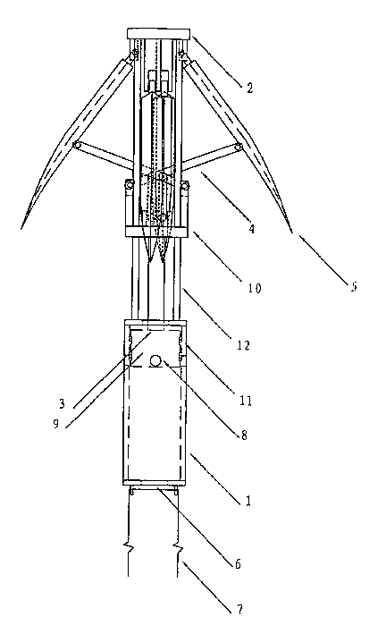
[0010] Such as figure 1 and figure 2 As shown, the present invention mainly comprises: steel pipe 1, anchor grab top seat 2, piston propulsion body 3, strut 4 and anchor grab 5, and its connection mode is: anchor grab top seat 2 and steel pipe 1 are connected by fixed pillar 12, four The two ends of the root strut 4 are respectively connected to the strut base 10 and the anchor grab 5 of the piston propelling body 3 by movable pins. The struts 4 are connected, and the anchor head rear portion is provided with a connecting hole to be connected with the anchor cable 7.

[0011] The tail of the steel pipe 1 is provided with a pressure grouting hole 6, and there are four reserved holes 8 on the upper part of the steel pipe 1. Pressure grouting from the pressure grouting hole 6 makes the anchor grab 5 open, and the slurry continues to enter through the four reserved holes 8. Anchor hole. Anchor grab top seat 2 is provided with four bearings. The piston propelling body 3 is com...


PUM


Abstract

This invention includes: thin wall steel tube, fluke top seat, piston propeller, bar and fluke in which the fluke top seat is fixedly connected with the thin wall steel tube, both ends of the bar are connected to its base seat of the piston probeller and fluke separately by flexible pins, the anchor head is linked to the fluke top seat by pins and middle of the fluke is linked with the bar, and connection holes connect the anchor chain at the back of the anchor head. Using the character of large fixed area and powerful force of fluke, this invention provides pulling resistance like anchor, in operation the back of anchor head is connected with the chain then put in anchor eyes to grout with high pressure from thin-wall steel tube to force the fluke open into the anchor eye wall to provide anchor force.

Description

technical field [0001] The invention relates to an anchor head of a soil anchor, in particular to a ship anchor type grouting expansion type soil anchor head, which belongs to the field of soil anchoring. Background technique [0002] Rock-soil anchoring technology can fully tap the energy of rock and soil itself, use its own strength and self-supporting capacity, ensure construction safety and structural stability, save engineering materials, and thus achieve significant economic benefits. The anchoring method in the natural soil layer is mainly drilling and grouting, which is generally called grouting anchor, and there are other forms such as soil nailing and wall anchoring. The anchor rod in the grouted soil layer is composed of an anchor rod (anchor cable), a free section, an anchor section, an anchor head, and a cushion block. The anchor section and the anchor head are the providers of the pull-out force, and their performance is related to the effect of the anchor rod...

Claims


Application Information

Patent Timeline
IPC IPC(8): E02D5/80E21D20/02
Inventor 葛修润黄铭
Owner SHANGHAI JIAO TONG UNIV
Learn More