Water supply and drainage pipeline for high-rise building

A high-rise building, water supply and drainage technology, applied in buildings, indoor sanitary plumbing installations, pipes, etc., can solve problems such as easy accumulation of large scale, inability to discharge sewage, loss of spiral strips to guide noise reduction, etc., and achieve the effect of avoiding loosening

Inactive Publication Date: 2022-08-09
钱圣
View PDF0 Cites 0 Cited by
  • Summary
  • Abstract
  • Description
  • Claims
  • Application Information

AI Technical Summary

Problems solved by technology

[0004] The purpose of the present invention is to provide a kind of water supply and drainage pipe for high-rise buildings to solve the problem that in most cases mentioned in the background art, the amount of sewage discharged in a single time in the building is relatively small. On the inner wall of the pipeline with a raised guide structure, a large amount of dirt is likely to accumulate in the concave area (that is, the side of the raised part). This type of dirt has strong adhesion and cannot be washed out directly through subsequent sewage discharge. After gradually accumulating, it is easy to cause The spiral strip loses its role of guiding and reducing noise, and it is very troublesome to clean the inner wall of the pipe in high-rise buildings

Method used


Image

  • Water supply and drainage pipeline for high-rise building
  • Water supply and drainage pipeline for high-rise building
  • Water supply and drainage pipeline for high-rise building

Examples


no. 1 example

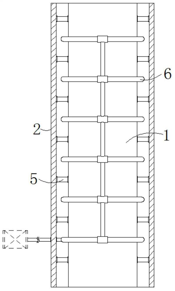
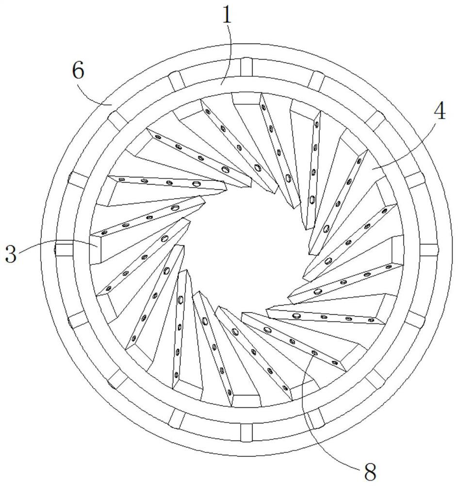
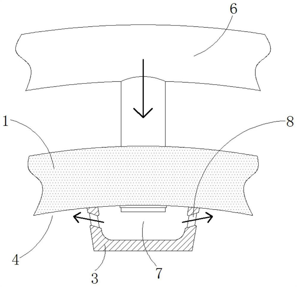
[0035] The pipeline includes an outer pipe 2 and an inner pipe 1 arranged inside the outer pipe 2, and the interconnected inner pipe 1 and the outer pipe 2 are arranged coaxially. The inner wall of the inner pipe 1 is provided with a guide strip 3. Between the guide strips 3 is the concave area 4 , the guide strip 3 and the adjacent concave area 4 jointly guide the water flow down the inner wall of the inner tube 1 along the spiral direction, and also include a buffer device, which is arranged on the outer tube 2 . The space between the inner wall and the outer wall of the inner tube 1 is used to buffer the impact of the water flow in the inner tube 1. In this embodiment, the buffer device is composed of a connecting column 5. The two ends of the connecting column 5 of the elastic structure are respectively connected to the outer tube. The inner wall of 2 and the outer wall of the inner pipe 1 are fixedly connected, and the ring pipe 6 is located between the upper and lower two...

no. 2 example

[0038] The difference from the first embodiment is that in this embodiment, in order to make the buffering effect better and the connection between the inner tube 2 and the outer tube 1 more stable, as Figure 4 As shown, the buffer device is the same spirally distributed buffer strip 9, the buffer strip 9 is fixed between the outer tube 2 and the inner tube 1, and the buffer strip 9 and the recessed area 4 are arranged correspondingly inside and outside, while the inner part of the elastic material buffer strip 9 A cavity 11 is provided, and the buffer device provided in this way can further alleviate the impact force by increasing the installation density. Although the cost is slightly higher than that of the first embodiment, its actual effect is as follows. part.

[0039] In this embodiment, the buffer bar 9 as the buffer device can not only buffer the impact force, but also play the role of conveying the circulating medium, such as Figure 5-6 As shown, the cavity 11 is ...

no. 3 example

[0041] The difference between this embodiment and the second embodiment is that the cleaning power source in this embodiment is mainly air flow, such as Figure 7-9 As shown, one end of the cavity 11 is communicated with the ring pipe 6, the cleaning device includes an air cavity 18 and an air hole 17, the other end of the cavity 11 is communicated with the air cavity 18 through the air hole 17, and the air hole 17 is opened on the outer wall of the inner pipe 1. , the air cavity 18 is opened at the concave area 4 and is also spirally distributed as the concave area 4, and the opening of the air cavity 18 is covered with an elastic sheet 19, the ring pipe 6 is connected with the air supply device, and the air supply device passes through the ring pipe 6 and The cavity 11 blows air intermittently into the air cavity 18, the air flow drives the elastic sheet 19 to deform and vibrate intermittently, and the fouling in the depression area 4 is vibrated and cleaned. The air supply d...


PUM


Abstract

The water supply and drainage pipeline for the high-rise building comprises an outer pipe and an inner pipe arranged in the outer pipe, guide strips are arranged on the inner wall of the inner pipe, and a concave area is formed between every two adjacent guide strips which are spirally distributed; the guiding strips and the adjacent sunken areas jointly guide water flow to flow downwards in the spiral direction on the inner wall of the inner pipe, and the buffering device is arranged between the inner wall of the outer pipe and the outer wall of the inner pipe and used for buffering impact of the water flow in the inner pipe. According to the water supply and drainage pipeline for the high-rise building, the pipeline is designed to be of an inner and outer double-layer structure, a buffer structure is designed between the double-layer structure, and a corresponding cleaning mechanism is arranged in the inner wall of the inner-layer structure, so that the inner wall of the pipeline can be cleaned by filling water or air; and meanwhile, an original concave area can become a new spiral guide structure through a corresponding expansion mode of a corresponding cleaning structure, and meanwhile, the surface can be cleaned.

Description

technical field [0001] The invention relates to the technical field of water supply and drainage of high-rise buildings, in particular to a water supply and drainage pipeline for high-rise buildings. Background technique [0002] When the drainage pipeline is actually used, it is necessary to consider the various effects of the flow of water on the pipeline, especially when it is used in high-rise buildings, it is necessary to consider the noise generated during the drainage process and the impact of water hammer on the pipeline when the water flow is large. In the prior art, in view of pipeline noise, in addition to wrapping sound insulation cotton on the outside of the pipeline, corresponding multi-strand convex spirally distributed guide strips are also arranged on the inner wall of the pipeline, so that the water can be guided spirally downward accordingly when it falls. flow, thereby reducing noise, but the existing similar pipes still have the following problems in act...

Claims


Application Information

Patent Timeline
Patent Type & Authority Applications(China)
IPC IPC(8): F16L9/18F16L55/027F16L55/045F16L55/24B08B9/032E03C1/122E03C1/308
CPCF16L9/18F16L55/02772F16L55/045F16L55/24B08B9/0321B08B9/0328E03C1/122E03C1/308E03C2201/60
Inventor 钱圣
Owner 钱圣
Why Eureka
Try Eureka