Flat gate valve with excellent sealing performance under low-pressure condition

A flat gate valve, low-pressure technology, applied in valve details, valve devices, sliding valves, etc., can solve the problems of entering the valve, poor sealing, low pressure, etc., to improve sealing, ensure abutment, and reduce gnawing phenomenon Effect

Active Publication Date: 2022-08-09
SHANGHAI HIGH & MEDIUM PRESSURE VALVE
View PDF5 Cites 0 Cited by
  • Summary
  • Abstract
  • Description
  • Claims
  • Application Information

AI Technical Summary

Problems solved by technology

However, there is a working condition, that is, the pressure of the liquid medium is small. At this time, if the O-ring is worn to a certain extent, and the valve seat and the gate are not tightly abutted, there will be liquid flowing from the valve seat and the gate. The case where the time enters the valve, that is, the sealing is poor

Method used


Image

  • Flat gate valve with excellent sealing performance under low-pressure condition
  • Flat gate valve with excellent sealing performance under low-pressure condition
  • Flat gate valve with excellent sealing performance under low-pressure condition

Examples


Embodiment 1

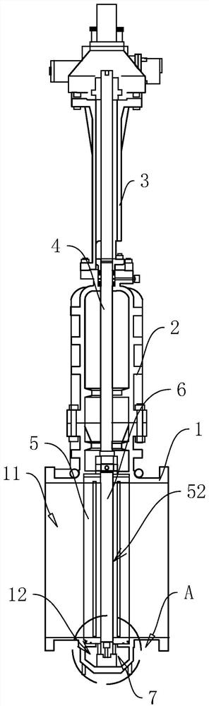
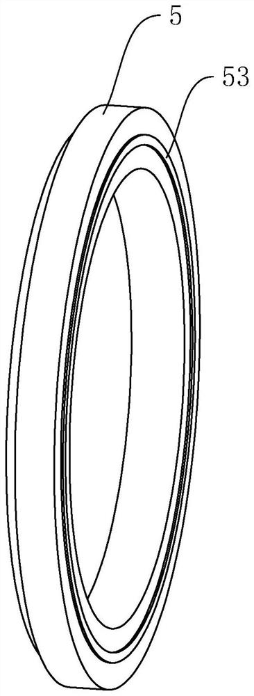
[0039] refer to figure 1 and figure 2, A flat gate valve with excellent sealing performance under low pressure conditions includes a valve body 1, a valve cover 2, a bracket 3, a valve stem 4, a floating valve seat 5 and a gate plate 6. The valve body 1 is provided with a flow chamber 11, and the valve cover 2 is connected to the upper side of the valve body 1 by bolts, the bracket 3 is fixed above the valve cover 2 by bolts, the valve stem 4 is lifted up and down in the bracket 3 and the valve cover 2, there are two floating valve seats 5, and the two float The edge of the valve seat 5 is provided with a trapezoidal groove 51 , and the two floating valve seats 5 abut in the flow chamber 11 of the valve body 1 through the trapezoidal groove 51 , and a lifting gap 52 is formed between the two floating valve seats 5 . The gate 6 is lifted and lowered within the lifting gap 52 , and the bottom of the valve stem 4 is fixedly connected with the upper side of the gate 6 .

[0040...

Embodiment 2

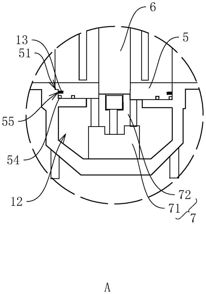
[0051] refer to Image 6 and Figure 7 The difference between this embodiment and Embodiment 1 is that the limit block 72 and the lower cushion block 71 are not fixedly connected by bolts, the lower cushion block is fixedly connected with a plug-in rod 711, and the limit block 72 is provided with a plug-in rod 71. The connecting rod 711 is inserted into the slot 721 for sliding fit, and the upper end of the connecting rod 711 is integrally formed with a limit piece 7111 , and the limit piece 7111 abuts against the top notch of the insertion slot 721 of the limit block 72 for preventing The limit block 72 is disengaged from the lower cushion block. The limit block 72 is located in the insertion slot 721 to form a contact surface 73 . The insertion rod 711 is sleeved with a buffer spring 9 , and one end of the buffer spring 9 is fixedly connected to the lower cushion block. , and the other end is fixedly connected to the contact surface 73 .

[0052] When the shutter 6 is clos...


PUM


Abstract

The invention discloses a flat gate valve with excellent sealing performance under the low-pressure condition, and relates to the field of flat gate valves, the flat gate valve comprises a valve body, two floating valve seats and a gate plate, a flowing cavity is formed in the valve body, the two floating valve seats abut against the interior of the flowing cavity of the valve body, and the gate plate is arranged in the flowing cavity of the valve body. A lifting gap is formed between the two floating valve seats, the flashboard ascends and descends in the lifting gap, the flashboard is matched with the two floating valve seats in an abutting mode, a containing cavity for containing the flashboard is formed in the position, located on the bottom side of the lifting gap, of the valve body, and the lower side of the flashboard is in a half-moon shape. O-shaped sealing rings are arranged on the sides, close to each other, of the two floating valve seats, when the flashboard ascends to be in a full-open state, the bottom side of the flashboard abuts against the O-shaped sealing rings on the two floating valve seats, and a limiting assembly used for preventing the bottom sides of the two floating valve seats from deviating is arranged in the position, located in the containing cavity, of the valve body. The sealing performance of the flat gate valve in a low-pressure state can be improved.

Description

technical field [0001] The present application relates to the field of flat gate valves, in particular to a flat gate valve with excellent sealing performance under low pressure conditions. Background technique [0002] At present, in the crude oil storage and transportation system, the flat gate valve is widely used, and the flat gate valve is a sliding valve whose closing part is a parallel gate. [0003] The existing flat gate valve includes a valve body, a valve seat and a gate. There are two valve seats, both of which are abutted on the valve body through a sealing ring. Lifting is within the lifting gap. When the gate rises, the valve opens to realize the delivery of liquid. When the gate falls, the valve closes to stop the delivery of liquid. O-rings are installed on the adjacent sides of the two valve seats, which are tightly pressed against the gate to achieve sealing. [0004] Since the valve seats in the existing flat gate valve are all floating, that is, when t...

Claims


Application Information

Patent Timeline
Patent Type & Authority Applications(China)
IPC IPC(8): F16K3/20F16K3/30F16K3/314F16K27/04
CPCF16K3/207F16K3/30F16K3/314F16K27/044Y02E10/20
Inventor 徐珍邓继林赵敏捷丁国于孔秉涛来蒙代静严权东张兆锟张林华
Owner SHANGHAI HIGH & MEDIUM PRESSURE VALVE
Why Eureka
Try Eureka