Buffering mechanism and material conveying device

A caching mechanism and material transmission technology, applied in conveyors, transportation and packaging, climate sustainability, etc., can solve the problems of motor speed response that is easy to keep up, equipment operation stability is poor, material belt is easy to shake, etc., to reduce Performance requirements, the effect of reducing jitter, and improving stability

Pending Publication Date: 2022-08-09
WUXI LEAD INTELLIGENT EQUIP CO LTD
View PDF5 Cites 0 Cited by
  • Summary
  • Abstract
  • Description
  • Claims
  • Application Information

AI Technical Summary

Problems solved by technology

[0004] Since the linear motor needs to move straight up and down during a group of motions (storage and release pole pieces), the response performance requirements of the linear motor are relatively high, and the speed response of the motor is likely to fail to keep up with high-speed conditions, and even abnormal noise occurs , when the material belt stops, it is easy to vibrate seriously, easy to break the belt, and there is a problem of poor equipment operation stability

Method used


Image

  • Buffering mechanism and material conveying device
  • Buffering mechanism and material conveying device
  • Buffering mechanism and material conveying device

Examples


Embodiment Construction

[0027] In order to facilitate understanding of the present application, the present application will be described more fully below with reference to the related drawings. Embodiments of the present application are presented in the accompanying drawings. However, the application may be implemented in many different forms and is not limited to the embodiments described herein. Rather, these embodiments are provided so that this disclosure will be thorough and complete.

[0028] Unless otherwise defined, all technical and scientific terms used herein have the same meaning as commonly understood by one of ordinary skill in the technical field to which this application belongs. The terms used herein in the specification of the application are for the purpose of describing specific embodiments only, and are not intended to limit the application.

[0029] It will be understood that the terms "first", "second", etc. used in this application may be used herein to describe various ele...


PUM


Abstract

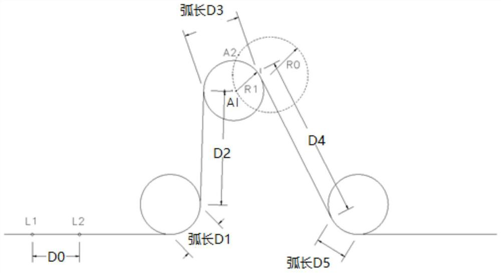
The invention relates to a temporary storage mechanism and a material conveying device. The temporary storage mechanism comprises a first front fixing roller, a first temporary storage roller, a first rear fixing roller, a second front fixing roller, a second temporary storage roller and a second rear fixing roller which are sequentially arranged in the running direction of a material conveying belt. The first front fixed roller, the first rear fixed roller, the second front fixed roller and the second rear fixed roller are located at the same horizontal position, the first buffer roller and the second buffer roller are located at the positions except the horizontal position where the first front fixed roller is located, and the first buffer roller and the second buffer roller are arranged in a mirror symmetry mode; the first buffer roller does non-uniform circular motion around a first preset circle center and a circle with a preset radius after being started; and the second buffer roller does non-uniform circular motion around a second preset circle center and a circle with a preset radius after being started. By adopting the method, the equipment operation stability can be improved.

Description

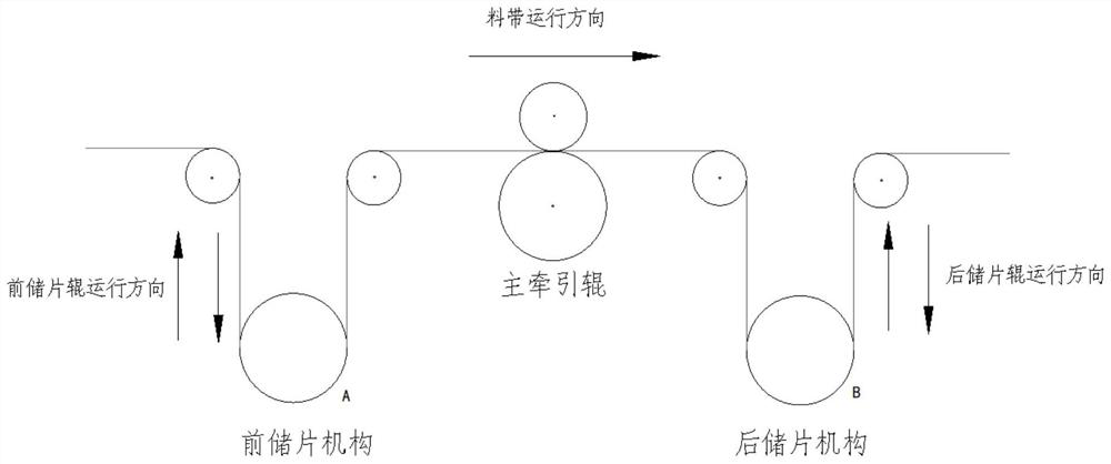
technical field [0001] The present application relates to the technical field of material production and transmission, and in particular, to a buffer mechanism and a material conveying device. Background technique [0002] In the production process of materials, sometimes it is necessary to process the materials in the transmission process, and for this purpose, a buffer mechanism is provided. The buffer mechanism is used to buffer the material during the conveying process, so as to realize the uniform transmission of the front and rear material belts, and the effect that the intermediate material belt can be started and stopped, so as to facilitate the technological processing of the material during the stop of the intermediate material belt. For example, a buffer mechanism is used to transport the pole pieces, and when the intermediate material belt stops, the pole pieces can be punched. [0003] The currently commonly used caching mechanisms are as follows figure 1 show...

Claims


Application Information

Patent Timeline
Patent Type & Authority Applications(China)
IPC IPC(8): B65G23/04B65G15/30B65G15/22
CPCB65G23/04B65G15/30B65G15/22Y02P70/50
Inventor 不公告发明人
Owner WUXI LEAD INTELLIGENT EQUIP CO LTD
Why Eureka
Try Eureka