Passive detection type nonreciprocal amplitude limiter

A non-reciprocal, limiter technology, applied in the direction of diode limit, advanced technology, climate sustainability, etc., can solve the problems that cannot meet the protection of transmitters and transceiver switches, achieve small insertion loss and improve power resistance effect of ability

Pending Publication Date: 2022-08-05
NAT UNIV OF DEFENSE TECH
View PDF0 Cites 0 Cited by
  • Summary
  • Abstract
  • Description
  • Claims
  • Application Information

AI Technical Summary

Problems solved by technology

At present, the research on limiters at home and abroad is mainly focused on integration, power resistance, etc., which cannot meet the protection requirements for transmitters and transceiver switches.

Method used


Image

  • Passive detection type nonreciprocal amplitude limiter
  • Passive detection type nonreciprocal amplitude limiter
  • Passive detection type nonreciprocal amplitude limiter

Examples


Embodiment Construction

[0029] In order to make the purposes, technical solutions and advantages of the embodiments of the present invention more clearly understood, the following will clearly illustrate the spirit of the disclosed contents of the present invention with the accompanying drawings and detailed description. Afterwards, changes and modifications can be made by the technology taught by the content of the present invention, without departing from the spirit and scope of the content of the present invention. The exemplary embodiments of the present invention and their descriptions are used to explain the present invention, but are not intended to limit the present invention.

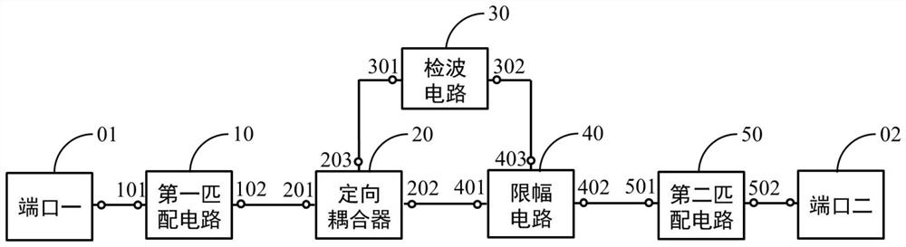
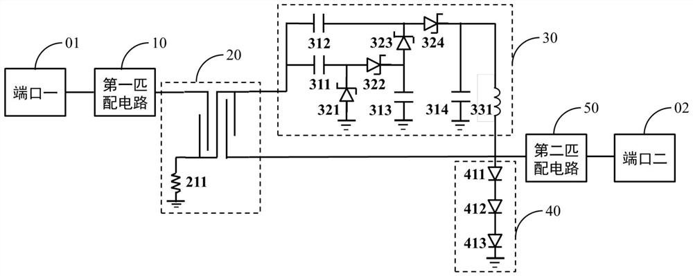
[0030] refer to figure 1 , the circuit structure of the passive detection type non-reciprocal limiter provided in an embodiment mainly includes a transceiver shared path, and the transceiver shared path includes a first input / output terminal, a directional coupler 20, and a limiter circuit connected in sequence. 40 a...


PUM


Abstract

The invention provides a passive detection type nonreciprocal amplitude limiter, which comprises a first input / output end, a directional coupler, an amplitude limiting circuit and a second input / output end which are connected in sequence, a detection circuit is connected between the directional coupler and the amplitude limiting circuit, and by utilizing the directivity of the directional coupler, when a receiving and transmitting shared path transmits a signal, the receiving and transmitting shared path transmits the signal; when the limiting level of the amplitude limiting circuit is higher than the transmitting power, the transmitting signal normally passes; when the receiving and transmitting shared path receives a signal, once the power of the received signal input from the directional coupler to the amplitude limiting circuit is greater than or equal to the starting limit level of the amplitude limiting circuit, the amplitude limiting circuit starts amplitude limiting, and the power of the signal input from the directional coupler to the amplitude limiting circuit is limited in a set range. The high-power signal amplitude limiter has small insertion loss on transmitted high-power signals and has a good amplitude limiting effect on received high-power signals, the problem that a traditional amplitude limiter can only be applied to a receiving channel can be effectively solved, and the power endurance capacity of a transmitting channel or a transceiving switch is improved.

Description

technical field [0001] The invention relates to the technical field of radio frequency circuits, in particular to a passive detection type non-reciprocal limiter. Background technique [0002] At present, the existing protection of the RF front-end is mainly based on the limiter. Since it does not have the non-reciprocal ability to transmit and receive, it can only be applied to the receiving channel, but not the transmitting channel. Therefore, the transmitter and the transceiver switch cannot be protected. Protect. Moreover, as the transceiver switches are gradually miniaturized and integrated, higher requirements are also placed on the power resistance performance. [0003] The action mechanism of the limiter is: when the input signal power is lower than the threshold level, the signal can pass normally. When the input signal exceeds the threshold level, the limiter limits the output signal to a certain range. For radars with integrated transceiver antennas, radar tran...

Claims


Application Information

Patent Timeline
Patent Type & Authority Applications(China)
IPC IPC(8): H03G11/02H04B1/40
CPCH03G11/02H04B1/40Y02D30/70
Inventor 沈健邓世雄林铭团刘继斌毋召锋李元鑫
Owner NAT UNIV OF DEFENSE TECH
Why Eureka
Try Eureka