
Novel movable heater

A mobile, heater technology, applied in heating methods, lighting and heating equipment, sustainable buildings, etc., can solve the problems of slow heating response, large heating temperature distribution gradient, and high heating temperature, and achieve accelerated heat loss and The effect of convection, small temperature distribution gradient and uniform heat distribution

Pending Publication Date: 2022-08-05
常熟亨通新能源产业研究院有限公司
View PDF0 Cites 0 Cited by
  • Summary
  • Abstract
  • Description
  • Claims
  • Application Information

AI Technical Summary

Problems solved by technology

[0002] There are two types of existing indoor heaters: hydrothermal floor heaters and electric heaters; among them, hydrothermal type: the heat source of the floor heater comes from the hot water of the gas wall-hung boiler, which is burned by natural gas and supplied with hot water for floor heating For heat dissipation; advantages: radiation heat dissipation, uniform heat distribution, and better human comfort; disadvantages: high operating costs, serious energy waste, slow response to heating, and need to turn on the heater for a long time in advance, which is harmful to indoor furniture or walls. The surface has a certain influence, and it is easy to produce peculiar smell. It needs to be installed in advance when decorating, and it takes up the indoor height. It is not suitable for the renovation of old houses, and it is difficult to maintain or repair later.
Disadvantages: electric heating has high temperature, which not only has potential safety hazards, but also has a short service life; the space and area covered by heat dissipation are small, the heat accumulation is serious, and the effective heating area is small; the heating temperature distribution gradient is large, and the overall comfort is poor

Method used


Image

  • Novel movable heater
  • Novel movable heater
  • Novel movable heater

Examples

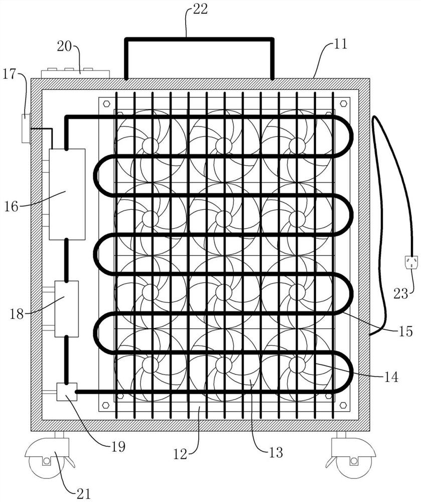
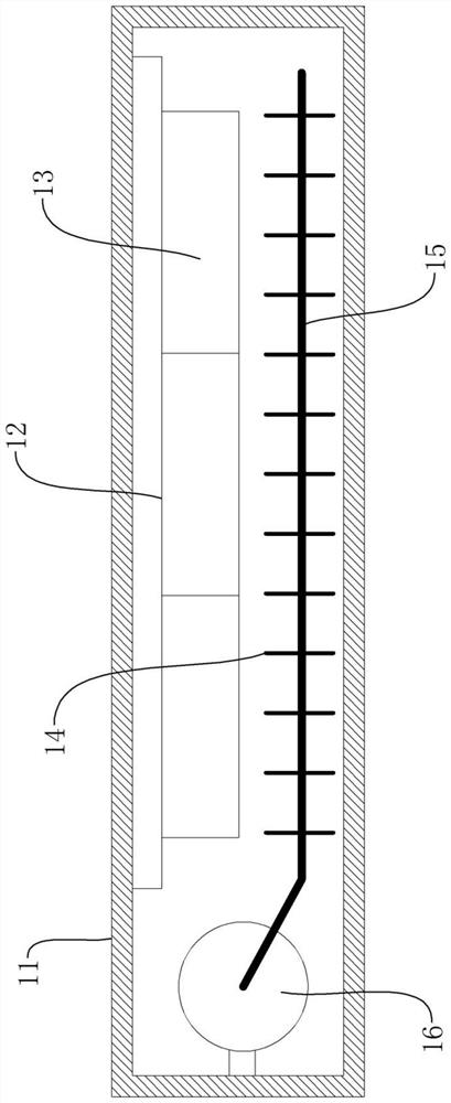
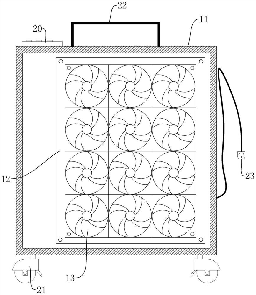

Embodiment Construction

[0024] The following combined with the attachment and the specific embodiments further explain the present invention, so that the technical personnel in the art can better understand the present invention and implement it, but the implementation examples are not limited to the invention.

[0025] Reference Figure 1-Figure 4 Show, an example of a new type of mobile heater in the present invention;

[0026] A new type of mobile thermor, including the main frame 11, the heat dissipation fan 13 and the radiator 10 inside the main frame 11, the front and back of the main frame 11 have the hollow structure for air circulation. In other words, the heat dissipation fan 13 can blow the air near the heat sink 10 to the outside of the main frame 11.

[0027] The heat dissipation fan 13 is used to drive air flow; the heat dissipation fan 13 includes the fan's blades and the fan blades installed on the motor, which drives the fan blades through the motor to promote the air flow. There is a hea...


PUM


Abstract

The invention discloses a novel movable heater which comprises a cooling fan, a heating device, a heating device, a heating device and a control device which are all mounted in a main frame body, and the cooling fan is used for driving air to flow; the radiator is communicated with the heat source system, a heat dissipation medium circulates in the radiator, the heat source system is used for heating and driving the heat dissipation medium to circularly flow in the radiator, and the heat dissipation medium transmits heat into air through the radiator. On one hand, heat in the radiator is dissipated into surrounding air in a radiation and convection mode through the high heat conductivity of the radiator, on the other hand, heat dissipation and convection are accelerated through uniform and continuous power provided by the cooling fan, and the heat is continuously conveyed into a large-space environment in a surface heat source mode; the large-space heat source area is firstly formed, the heat source area radiates and transfers heat to the periphery, the covered space and area are large, the temperature distribution gradient is small, heat is evenly dispersed, and the comfort of human body feeling is good.

Description

Technical field [0001] The invention involves the technical field of heating equipment, which specifically involves a new type of mobile heater. Background technique [0002] The existing indoor heaters include two types: water -heat type heater and electrical heating heater. Among them, the heat source of the water heater comes from the hot water of the gas wall -mounted boiler. Heat dissipation; advantages: radiation heat dissipation, uniform heat distribution, good comfort of the human body; disadvantages: extremely high operating costs, serious energy waste, slow heating reactions The surface has a certain impact, which is easy to produce odor. It is necessary to install it in advance during decoration, occupy the indoor height, is not suitable for the transformation of old houses, and it is difficult to operate maintenance or maintenance in the later stage. For electrical heating: traditional electric heating heater include metal heating heating, carbon crystal heating heate...

Claims


Application Information

Patent Timeline
Patent Type & Authority Applications(China)
IPC IPC(8): F24D13/04F24D19/02
CPCF24D13/04F24D19/0243F24D2200/08Y02B30/00
Inventor 王永忠
Owner 常熟亨通新能源产业研究院有限公司
Learn More