
Composite lining structure of high-pressure diversion tunnel

A water diversion tunnel and composite lining technology, applied in the field of tunnel engineering, can solve the problems of ignoring the load bearing effect of the support layer and the waste of hydraulic tunnel construction

Pending Publication Date: 2022-08-05
CHINA INST OF WATER RESOURCES & HYDROPOWER RES +2
View PDF6 Cites 0 Cited by
  • Summary
  • Abstract
  • Description
  • Claims
  • Application Information

AI Technical Summary

Problems solved by technology

[0006] However, in fact, during the operation period of the hydraulic tunnel, the support layer can still play a certain load-bearing role, ignoring the load-bearing role of the support layer during the operation period will inevitably cause huge waste to the construction of the hydraulic tunnel

Method used


Image

  • Composite lining structure of high-pressure diversion tunnel
  • Composite lining structure of high-pressure diversion tunnel
  • Composite lining structure of high-pressure diversion tunnel

Examples


Embodiment Construction

[0024] The structure and features of the present invention will be described in detail below with reference to the accompanying drawings and embodiments. It should be noted that various modifications can be made to the embodiments disclosed herein, therefore, the embodiments disclosed in the specification should not be regarded as limitations of the present invention, but only as examples of embodiments, the purpose of which is to make the present invention The features of the invention are obvious.

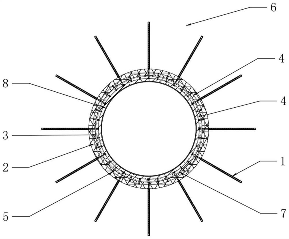
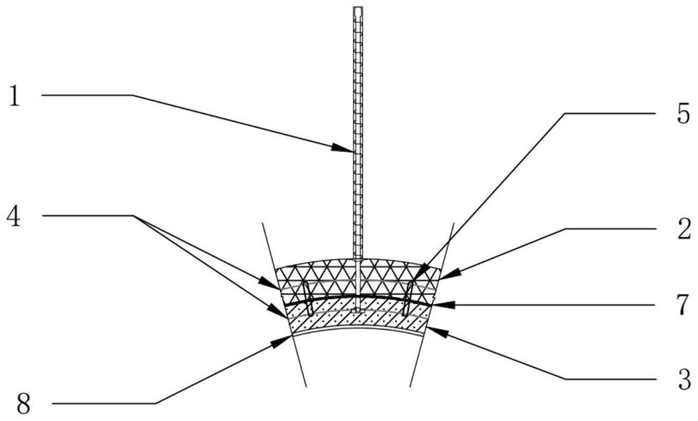
[0025] like Figure 1-Figure 3 As shown, the novel high-pressure water diversion tunnel composite lining structure disclosed in the present invention includes an anchor rod 1 , a supporting layer 2 , a lining layer 3 , a carbon fiber reinforcement 4 and a connecting reinforcement 5 .

[0026] The bolt 1 is driven into the surrounding rock 6 around the tunnel, and its function is to strengthen and protect the surrounding rock and improve the bearing capacity and self-supporting c...


PUM


Abstract

The invention provides a composite lining structure of a high-pressure diversion tunnel. The composite lining structure comprises anchor rods, a supporting layer, a lining layer, carbon fiber ribs and connecting ribs. The anchor rod is driven into surrounding rock around the tunnel, and the tail of the anchor rod penetrates through the supporting layer and extends to the lining layer; the supporting layer is tightly attached to the inner wall of the tunnel and is formed by spraying construction of SFRS steel fiber reinforced sprayed concrete; the lining layer is located on the supporting layer and formed by pouring SFRC steel fiber reinforced concrete. Carbon fiber ribs are embedded in the supporting layer and the lining layer and fixedly connected with the tail of the anchor rod, and connecting ribs used for connecting the carbon fiber ribs in the supporting layer and the lining layer together are further embedded in the supporting layer and the lining layer. Due to the fact that the carbon fiber ribs are embedded in the supporting layer and the lining layer, and the carbon fiber ribs in the supporting layer and the lining layer are connected through the connecting ribs, the supporting layer and the lining layer are combined together to jointly bear the pressure load of water flow in the tunnel to the tunnel in the operation period of the diversion tunnel, and therefore the purpose of reducing the thickness of the lining layer is achieved.

Description

technical field [0001] The present invention relates to a composite lining structure for a high-pressure water diversion tunnel, in particular to a high-pressure water diversion tunnel composite lining structure that fully exerts the bearing function of a support layer during the operation period of the high-pressure water diversion tunnel and reduces the thickness of the lining layer. The invention belongs to the technical field of tunnel engineering. Background technique [0002] High-pressure water diversion tunnels have been widely used in the field of hydraulic structure engineering. For deeply buried high-pressure water diversion tunnels, the lining structure is affected by large buried depth, large cross-section, long tunnel line, high ground stress, abundant groundwater and high water head. Due to the influence of factors, the design and construction of its lining structure are faced with huge challenges and difficulties. [0003] In the construction of deep-buried ...

Claims


Application Information

Patent Timeline
Patent Type & Authority Applications(China)
IPC IPC(8): E21D11/00E21D11/10E21D11/38E21D20/00
CPCE21D11/00E21D11/105E21D11/107E21D11/383E21D20/00Y02E10/20
Inventor 邓检强张翔宇杜三林崔炜朱银邦杨传根邵堃刘毅朱新民刘有志
Owner CHINA INST OF WATER RESOURCES & HYDROPOWER RES
Learn More