
Chip mounter automatic calibration system

An automatic calibration and placement machine technology, which is applied in the direction of climate sustainability, final product manufacturing, electrical components, etc., can solve problems such as deviation of the bonding position, misalignment of the output end of the processing component and the bonding component, etc., to achieve Good processing effect, easy to adjust and control processing, and improve the effect of calibration effect

Active Publication Date: 2022-08-02
安徽丰士通电子科技有限公司
View PDF6 Cites 0 Cited by
  • Summary
  • Abstract
  • Description
  • Claims
  • Application Information

AI Technical Summary

Problems solved by technology

[0003] Existing conveyor belt placement machines such as Figure 5 As shown, the components are placed on the upper end of the conveyor belt for transmission, and the components to be bonded are attached to the upper end of the components through the processing components to complete the bonding effect of the components. Improper, resulting in the misalignment of the output end of the processing component and the bonding component, causing the position of the bonding to deviate, and a good blocking mechanism is not set inside to limit and block the components, so that the components stop at the designated area and the processing component is completed. Precise fit processing

Method used


Image

  • Chip mounter automatic calibration system
  • Chip mounter automatic calibration system
  • Chip mounter automatic calibration system

Examples


Embodiment Construction

[0023] The technical solutions of the present invention will be clearly and completely described below with reference to the embodiments. Obviously, the described embodiments are only a part of the embodiments of the present invention, rather than all the embodiments. Based on the embodiments of the present invention, all other embodiments obtained by those of ordinary skill in the art without creative efforts shall fall within the protection scope of the present invention.

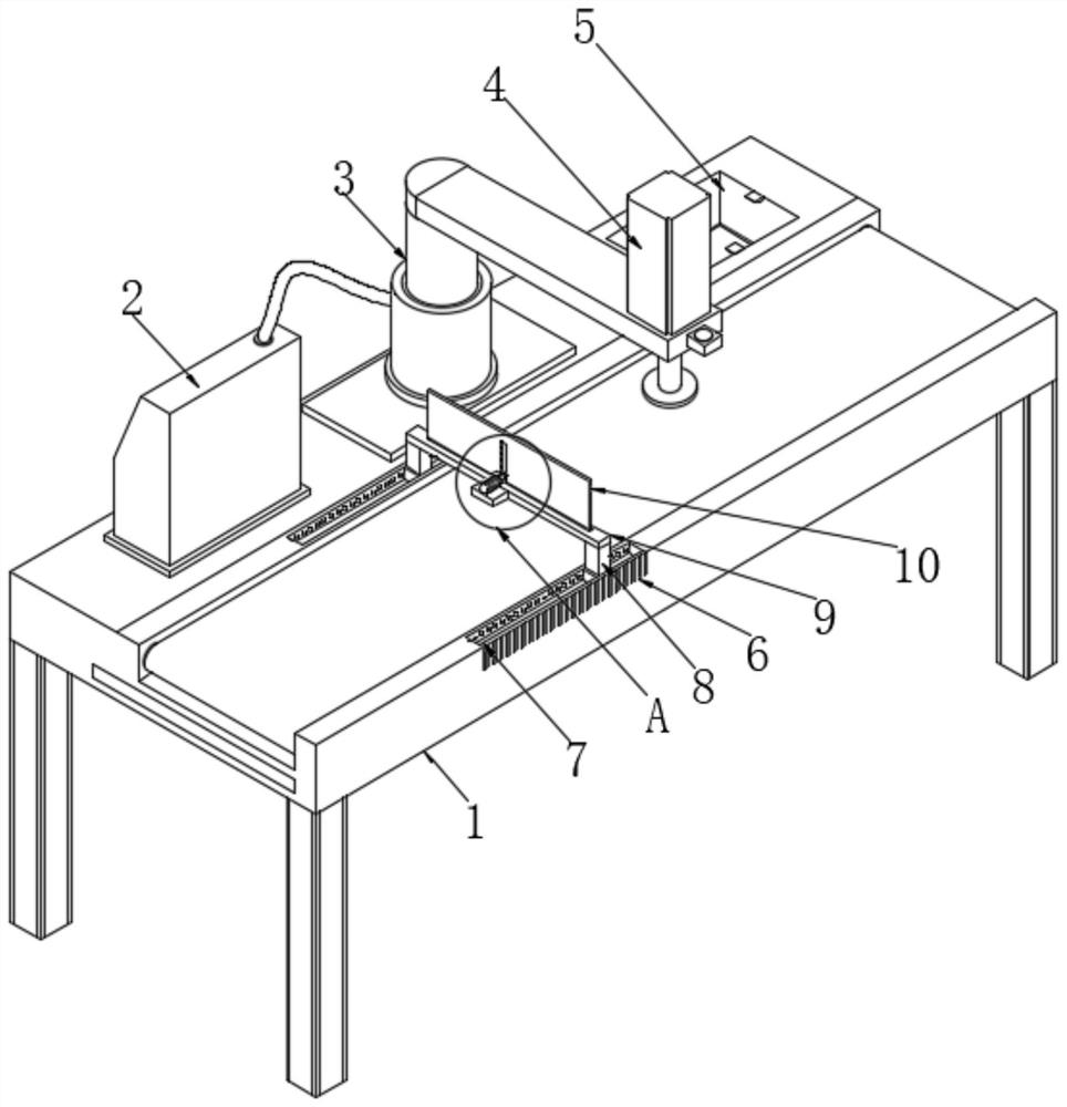
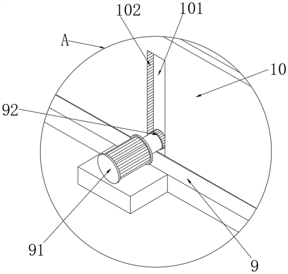
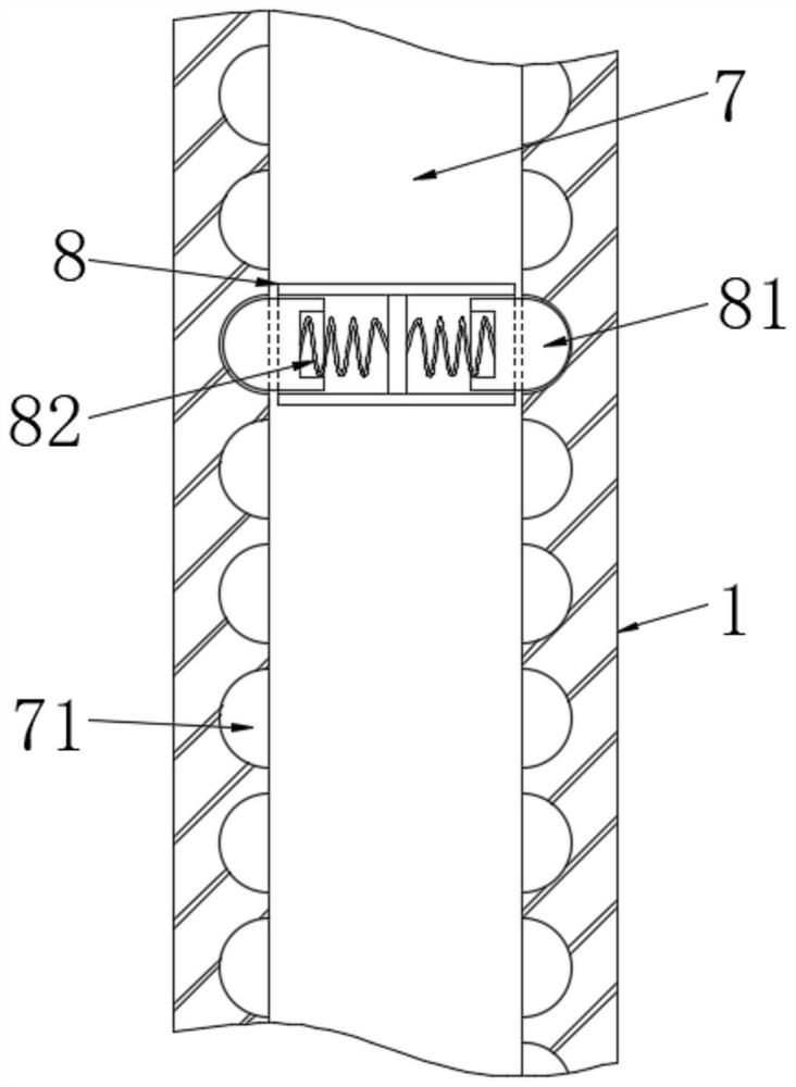
[0024] see figure 1 , the application provides an automatic calibration system for a placement machine, including a frame 1, a rotator 3 and a console 2, the rotator 3 is located in the middle of one side of the upper end of the frame 1, and the console 2 is located on one side of the rotator 3, so Both sides of the upper end of the frame 1 are provided with sliding grooves 7, and a sliding block 8 is slidably connected inside the sliding groove 7, and a sliding engaging mechanism is arranged between the...


PUM


Abstract

The invention discloses an automatic calibration system of a chip mounter, relates to the technical field of chip mounters, and solves the technical problem that when the output end of a processing assembly is not aligned with a fitting assembly, the fitting position deviates. A circuit switch of a rotating motor is turned on, an output transmission shaft is driven to rotate, the output transmission shaft is in meshed connection with a sliding baffle through meshing teeth and drives the sliding baffle to move up and down, the sliding baffle can move to a conveying belt in the up-down sliding process, and when the conveying belt conveys accessories, the sliding baffle slides to the lowest end; the accessory can be blocked by rotating the suction pad, so that the blocking effect is achieved, the suction pad is aligned with the center position of the accessory, the calibration effect is achieved, the calibration effect is improved, and then the sticker is adsorbed through the processing assembly and attached to the designated position of the accessory.

Description

technical field [0001] The invention belongs to the technical field of placement machines, in particular to an automatic calibration system for placement machines. Background technique [0002] Mounter: Also known as "mounter", in the production line, it is configured after the glue dispenser or screen printer, and is a kind of accurately placing surface mount components on the PCB pads by moving the mounting head. Equipment, divided into manual and automatic two. [0003] Existing conveyor belt placement machines such as Figure 5 As shown in the figure, the components are placed on the upper end of the conveyor belt for transmission, and the components to be attached are attached to the upper end of the components through the processing components to complete the attachment effect of the components. Improper, resulting in the misalignment of the output end of the processing component and the fitting component, making the fitting position deviate, and there is no good inte...

Claims


Application Information

Patent Timeline
Patent Type & Authority Applications(China)
IPC IPC(8): H05K3/30H05K13/04H05K13/02
CPCH05K3/30H05K13/0417H05K13/02Y02P70/50
Inventor 武其俊张华高清祥
Owner 安徽丰士通电子科技有限公司
Learn More