Punching-free monitoring camera convenient to fix
A surveillance camera, punch-free technology, applied in the field of surveillance cameras, can solve the problems of enlarged rust area, prone to rust, large-scale use, etc. Effect
- Summary
- Abstract
- Description
- Claims
- Application Information
AI Technical Summary
Problems solved by technology
Method used
Image
Examples
Embodiment 1
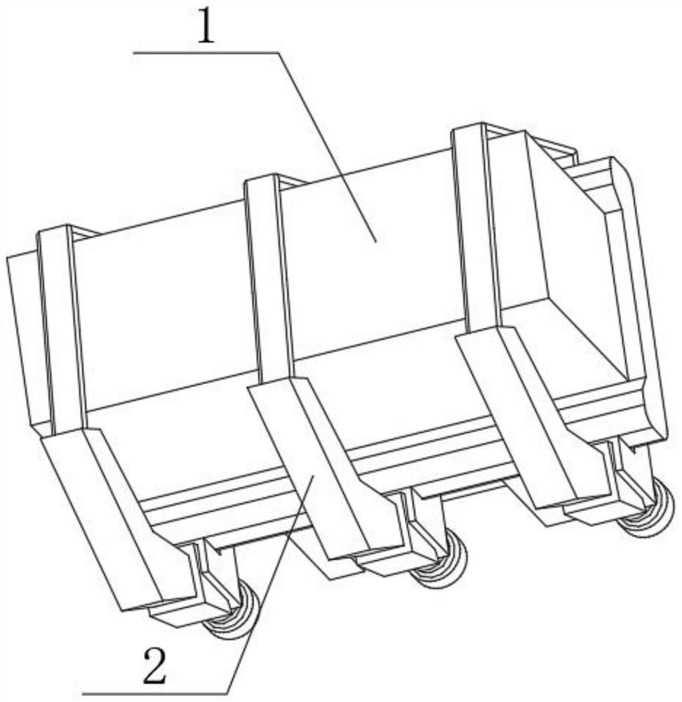
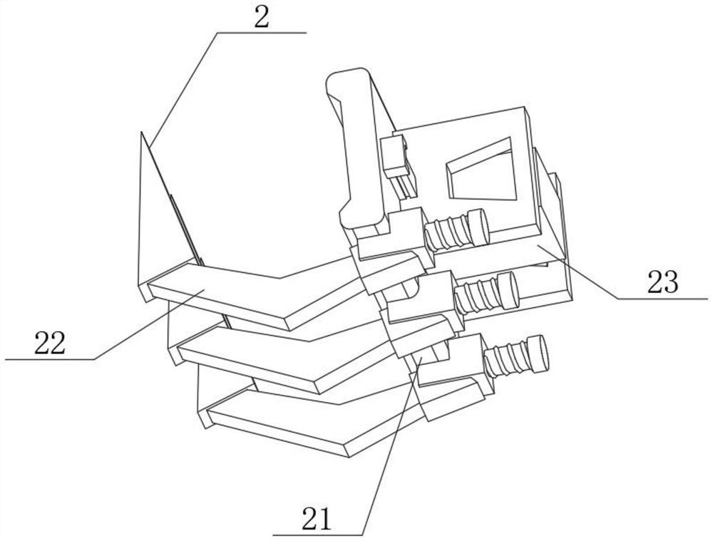
[0039] Example 1: as figure 1 , figure 2 and Figure 5 As shown, a surveillance camera that is easy to fix without punching includes a camera device 1 and a camera fixing device 2, the camera device 1 is located inside the camera fixing device 2, and the camera fixing device 2 includes a support structure 21, a position defining structure 22 and a docking Frame 23, one end of the position defining frame 22 is connected to the bottom of the supporting frame 21, the docking frame 23 is installed on the back of the supporting frame 21, the camera device 1 is located inside the position defining frame 22, the supporting frame 21 includes a bearing panel 211, the bearing panel 211 An accommodating groove 212 is opened on one side of the accommodating groove 212, and a non-slip synapse 213 is arranged inside the accommodating groove 212. The camera device 1 is located between the carrying panel 211 and the secondary fixing structure 224, and the anti-slip synapse 213 is located be...
Embodiment 2
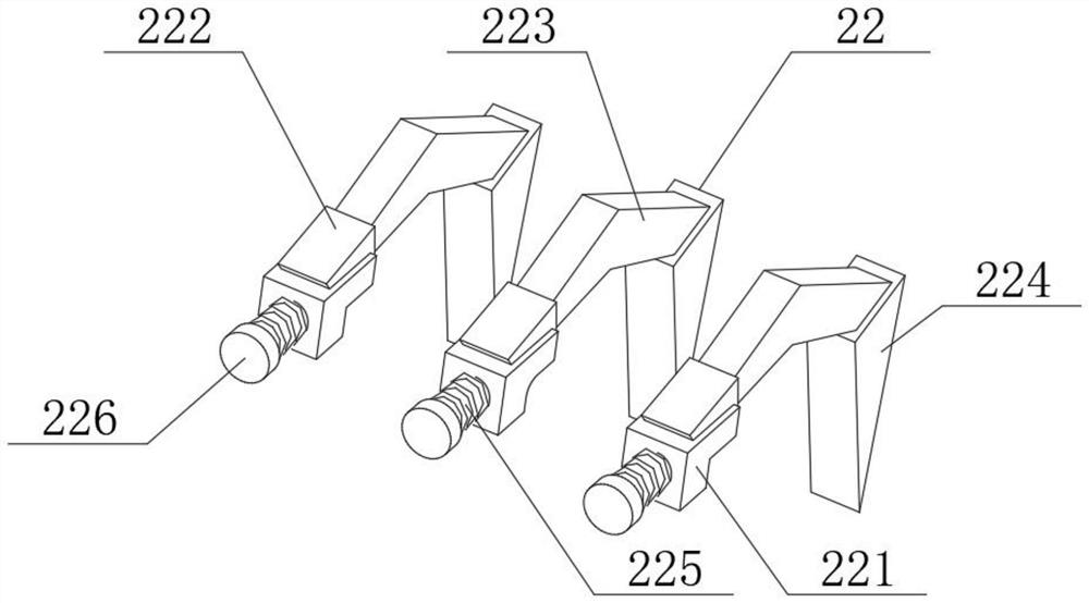
[0041] Example 2: as image 3 and Figure 4 As shown, the position limiting structure 22 includes a connection port 221, a rotating block 222, a primary limiting rod 223, a secondary fixing structure 224, an elastic trigger rod 225 and a push panel 226. The rotating block 222 is installed inside the connecting port 221, and the primary One end of the limiting rod 223 is connected to the inside of the rotating block 222, one end of the secondary fixing structure 224 is connected to the other end of the primary limiting rod 223, the elastic trigger rod 225 is installed on the other side of the connection port 221, and the propulsion panel 226 is installed on the other side of the connecting port 221. On the other end of the elastic trigger lever 225, the secondary fixing structure 224 includes a fixing shaft 2241, a rubber band 2242, a plug port 2243, a accommodating box 2244, an adsorption magnet 2245 and a receiving groove 2246. One end of the rubber band 2242 is connected to ...
Embodiment 3
[0043] Example 3: as Image 6 , Figure 7 As shown, the docking structure 23 includes a retractable panel 231 , a fixed center 232 , a diffusion structure 233 , a guide slide bar 234 and a restriction port 235 , the restriction port 235 is installed at one end of the guide slide bar 234 , and the retractable panel 231 is installed on the guide slide bar 234 . At the top, the inside of the shrink panel 231 is provided with a limiting through hole, the fixing center 232 is located inside the shrink panel 231, the diffusion frame 233 is installed on both sides of the fixing center 232, and the diffusion frame 233 is located at the intersection of the fixing center 232 and the shrink panel 231, The diffusion structure 233 includes a depression port 2331 , a middle limit disc 2332 , a movable transmission rod 2333 , a connecting piston 2334 , a torsion spring 2335 and a diffusion snap block 2336 , the depression port 2331 is installed on the top of the middle limit disk 2332 , and ...
PUM
 Abstract
Description
Claims
Application Information
 - R&D
- Intellectual Property
- Life Sciences
- Materials
- Tech Scout
- Unparalleled Data Quality
- Higher Quality Content
- 60% Fewer Hallucinations
Browse by: Latest US Patents, China's latest patents, Technical Efficacy Thesaurus, Application Domain, Technology Topic, Popular Technical Reports.
© 2025 PatSnap. All rights reserved.Legal|Privacy policy|Modern Slavery Act Transparency Statement|Sitemap|About US| Contact US: help@patsnap.com


