
Pressure-stabilizing switchable multi-section fuel injection system and method

A fuel injection and switching technology, applied in the direction of fuel injection device, fuel injection control, charging system, etc., can solve the problems of inability to control combustion well, lack of coherence and continuity, and increase the injection time, etc. The effect of improving fuel combustion efficiency, improving combustion efficiency, and expanding the volume of high-pressure oil

Active Publication Date: 2022-08-02
DONGFENG COMML VEHICLE CO LTD
View PDF4 Cites 0 Cited by
  • Summary
  • Abstract
  • Description
  • Claims
  • Application Information

AI Technical Summary

Problems solved by technology

[0006] Existing technology requires precise and connected control of pre-injection, main injection, and post-injection. At present, in the process of diesel fuel injection, diesel engine fuel injection is divided into pre-injection, main injection, and post-injection, and each section of injection is only used once. And there is no coherence and continuity, and each injection controls the fuel injection according to the power-on time of the normally closed solenoid valve, but as the injection progresses, the pressure of the fuel rail gradually decreases, so the fuel system has high requirements on the rail pressure, but Due to the opening of the normally closed solenoid valve in the high-pressure oil circuit, there will be head loss when the fuel fluid is injected into the cylinder, and the rail pressure will drop during the single injection sequence, resulting in a gap between the actual fuel injection quantity and the expected fuel injection. The duration, can not control the combustion well

Method used


Image

  • Pressure-stabilizing switchable multi-section fuel injection system and method
  • Pressure-stabilizing switchable multi-section fuel injection system and method
  • Pressure-stabilizing switchable multi-section fuel injection system and method

Examples


Embodiment Construction

[0042] The specific embodiments of the present invention will be further described below with reference to the accompanying drawings. It should be noted here that the descriptions of these embodiments are used to help the understanding of the present invention, but do not constitute a limitation of the present invention. In addition, the technical features involved in the various embodiments of the present invention described below can be combined with each other as long as there is no conflict with each other.

[0043] Where "including", "having" and "comprising" are used as described in this specification, unless otherwise used, there may be another part or other parts, and the terms used may generally be singular but may also refer to the plural.

[0044] The features of the various embodiments of the present invention may be combined or spliced ​​with each other, in part or in whole, and may be implemented in various configurations as will be well understood by those skill...


PUM


Abstract

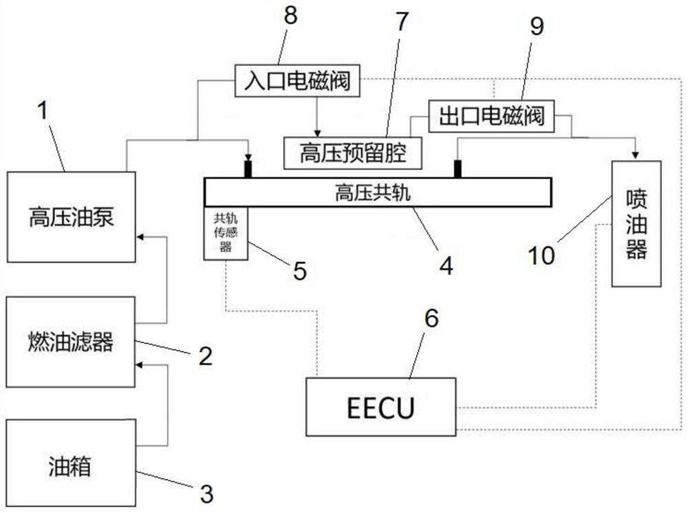
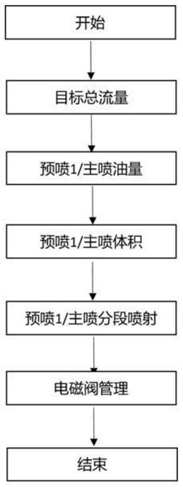
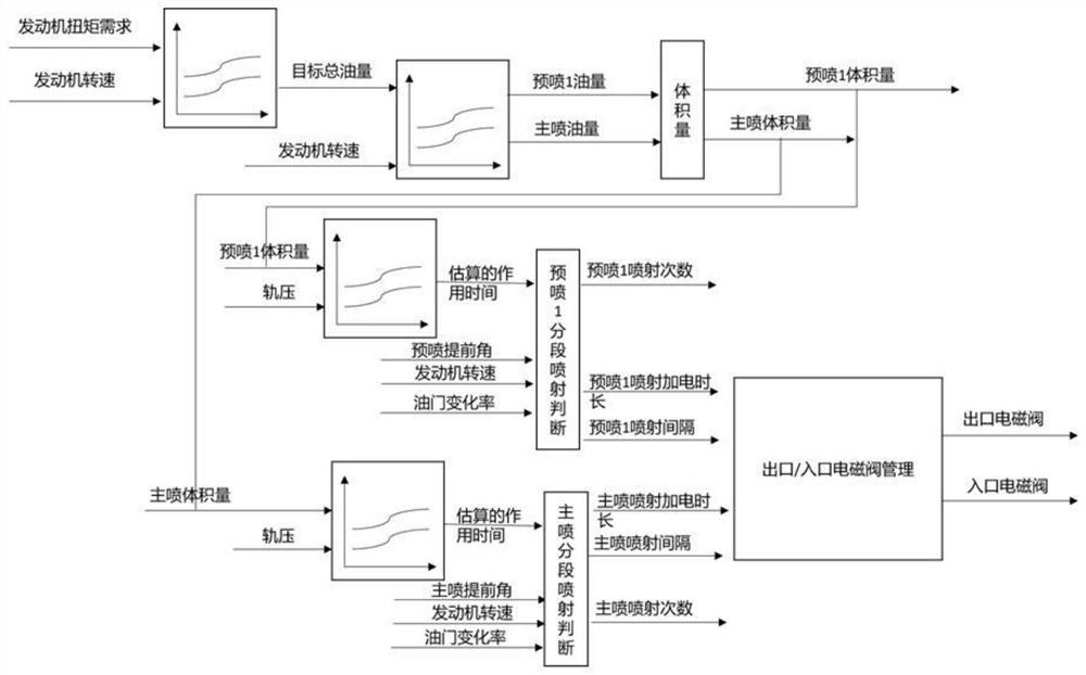
The invention discloses a pressure-stabilizing switchable multi-section fuel injection system and method. The high-pressure oil pump is used for pumping fuel oil in an oil tank into a high-pressure reserved cavity and a high-pressure common rail; the high-pressure common rail is used for providing high-pressure oil to the oil injector; the high-pressure reserved cavity is used for pre-storing high-pressure oil and guiding the high-pressure oil into the oil injector when multi-section injection is needed; the inlet electromagnetic valve is mounted on a public pipeline, communicated with the high-pressure oil pump and the high-pressure common rail, of the high-pressure reserved cavity; the outlet electromagnetic valve is mounted on a public pipeline through which the high-pressure reserved cavity is communicated with the high-pressure common rail and the oil sprayer; the oil injector is used for injecting high-pressure oil; the engine control unit is used for collecting vehicle parameters, determining injection parameters according to the vehicle parameters, controlling opening and closing of the inlet electromagnetic valve and the outlet electromagnetic valve according to the injection parameters, and conducting multi-section fuel injection control. By means of the pressure storage function of the high-pressure reserved cavity, it is guaranteed that the fuel oil injection time is shortened, and the fuel oil combustion efficiency is improved.

Description

technical field [0001] The invention belongs to the technical field of automobile engine control, and in particular relates to a voltage-stabilizing switchable multi-stage fuel injection system and method. Background technique [0002] The high-pressure common rail system uses the common rail pipe between the high-pressure fuel pump and the injector to accumulate the fuel output from the high-pressure fuel pump and suppress pressure fluctuations, and then deliver the fuel to each injector through each high-pressure fuel pipe. The action of the solenoid valve on the injector controls the start and termination of the injection, the time when the solenoid valve works determines the injection timing, and the duration of the action and the common rail pressure together determine the injection quantity. [0003] Pre-injection 1 precedes the main injection, and the pre-injection results: the mixture pressure in the cylinder increases slightly; the delay in the main injection combus...

Claims


Application Information

Patent Timeline
Patent Type & Authority Applications(China)
IPC IPC(8): F02D41/38F02M51/00F02M63/00
CPCF02D41/3827F02D41/3836F02M51/00F02M63/00F02M63/0012Y02T10/40
Inventor 张明张晓光刘振华张威徐丹王梅俊龙祥
Owner DONGFENG COMML VEHICLE CO LTD
Learn More