
Grabbing device of segment erector

A segment assembly machine and grabbing device technology, which is applied in shaft equipment, shaft lining, mining equipment, etc., can solve problems such as low efficiency, low degree of automation, and hidden dangers of manual operation and installation, and achieve the goal of ensuring worker safety and high efficiency Effect

Pending Publication Date: 2022-08-02
CHINA RAILWAY ENGINEERING EQUIPMENT GROUP CO LTD
View PDF2 Cites 0 Cited by
  • Summary
  • Abstract
  • Description
  • Claims
  • Application Information

AI Technical Summary

Problems solved by technology

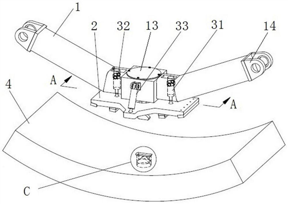
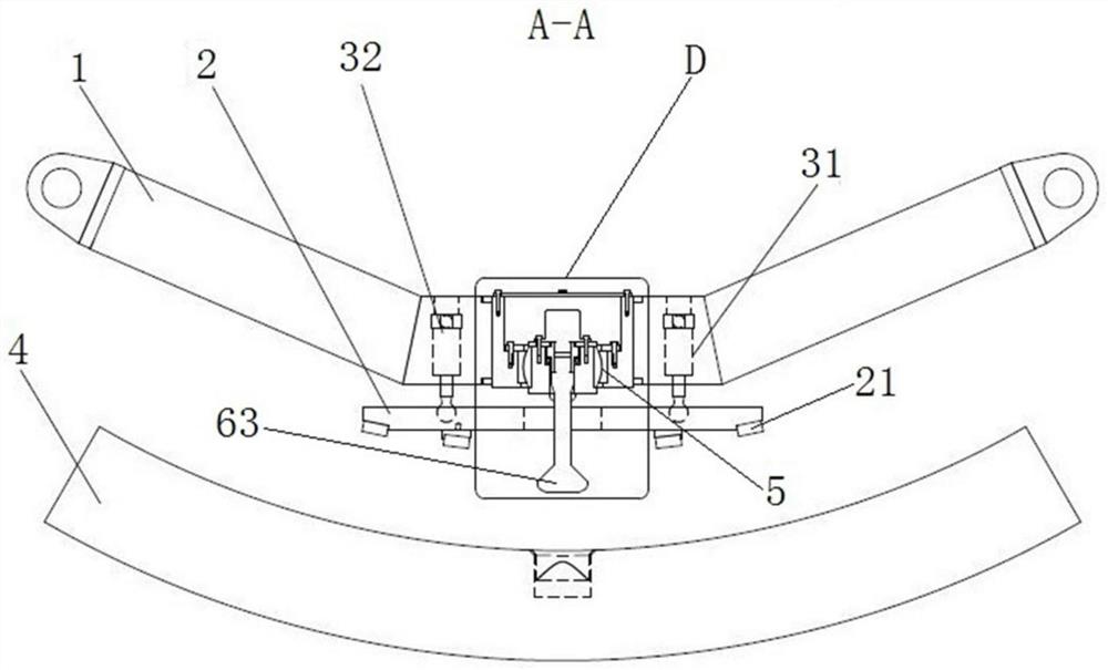
[0005] The purpose of the present invention is to provide a grabbing device for a segment assembly machine to solve the problems of low automation, low efficiency, and hidden dangers in manual operation of the segment assembly machine in the prior art.

Method used


Image

  • Grabbing device of segment erector
  • Grabbing device of segment erector
  • Grabbing device of segment erector

Examples


Embodiment Construction

[0042] In order to make the objectives, technical solutions and advantages of the present invention clearer, the present invention will be further described in detail below with reference to the accompanying drawings and embodiments. It should be understood that the specific embodiments described herein are only used to explain the present invention, but not to limit the present invention, that is, the described embodiments are only a part of the embodiments of the present invention, rather than all the embodiments. The components of the embodiments of the invention generally described and illustrated in the drawings herein may be arranged and designed in a variety of different configurations.

[0043] Thus, the following detailed description of the embodiments of the invention provided in the accompanying drawings is not intended to limit the scope of the invention as claimed, but is merely representative of selected embodiments of the invention. Based on the embodiments of t...


PUM


Abstract

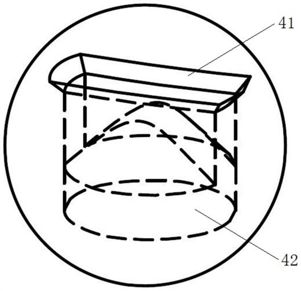
The invention relates to the technical field of pipe piece erectors for tunneling, in particular to a pipe piece erector grabbing device which comprises a grabbing beam, a first driving mechanism for driving a rotating shaft to rotate and a pressing disc located below the grabbing beam. A second driving mechanism for driving the pressure plate to move up and down is connected between the pressure plate and the grabbing beam; the rotating shaft comprises a rotating rod penetrating through the pressing disc, the lower end of the rotating rod is provided with a grabbing head which penetrates through an insertion opening in the duct piece, stretches into a grabbing cavity of the duct piece and rotates, the grabbing head is located below the pressing disc, and the grabbing head is provided with a stopping face which is arranged upwards and matched with the upper cavity wall of the grabbing cavity in a stopping mode. The pressing disc is provided with a pressing face which is arranged downwards and used for pressing the segment surface and is matched with the stopping face to clamp the segment. Automatic operation can be achieved, the duct piece bolt does not need to be screwed into a duct piece bolt hole manually, the duct piece bolt does not need to be hung on a lifting appliance manually, efficiency is higher, and the safety of workers can be guaranteed.

Description

technical field [0001] The invention relates to the technical field of segment assembling machines for tunnel excavation, in particular to a grabbing device for a segment assembling machine. Background technique [0002] After the shield machine excavates the tunnel, it is necessary to install the segment in the tunnel to prevent the tunnel from collapsing. The segment is transported into the tunnel through the segment conveying track, and then transported to the back of the cutter head by the segment hanger, and finally the pipe behind the cutter head The segment assembling machine installs the segments in the corresponding positions, that is, the segment assembling machine assembles the segments into a section of pipeline, and the segments need to be picked up before assembling the segments. At present, the grasping device of the assembly machine can be mainly divided into two types: vacuum suction cup type and mechanical type. [0003] For example, the Chinese invention ...

Claims


Application Information

Patent Timeline
IPC IPC(8): E21D11/40E21D11/08
CPCE21D11/40E21D11/08
Inventor 郭沛霖胡燕伟付超王坤宁郑康泰李豪锴
Owner CHINA RAILWAY ENGINEERING EQUIPMENT GROUP CO LTD
Learn More