
Permanent magnet synchronous motor rotor position and speed detection method based on orthogonal phase-locked loop

A permanent magnet synchronous motor and rotor position technology, applied in the direction of AC motor control, generator control, motor generator control, etc., can solve the problems of amplitude deviation, phase deviation, etc., and achieve the elimination of calculation errors, low cost, and system The effect of simple structure

Pending Publication Date: 2022-07-29
NANJING UNIV OF AERONAUTICS & ASTRONAUTICS
View PDF0 Cites 0 Cited by
  • Summary
  • Abstract
  • Description
  • Claims
  • Application Information

AI Technical Summary

Problems solved by technology

[0004] Purpose of the invention: The purpose of the present invention is to provide a permanent magnet synchronous motor rotor position and speed detection method based on a quadrature phase-locked loop, which solves the problem of the existence of amplitude values ​​among multiple Hall signals in the traditional rotor position detection scheme of permanent magnet synchronous motors. The problem of deviation and phase deviation, the algorithm is simple to implement, the system structure is simple and robust

Method used


Image

  • Permanent magnet synchronous motor rotor position and speed detection method based on orthogonal phase-locked loop
  • Permanent magnet synchronous motor rotor position and speed detection method based on orthogonal phase-locked loop
  • Permanent magnet synchronous motor rotor position and speed detection method based on orthogonal phase-locked loop

Examples


Embodiment Construction

[0042] Below in conjunction with accompanying drawing, the technical scheme of the present invention is described in further detail:

[0043] The present invention may be embodied in many different forms and should not be considered limited to the embodiments described herein. Rather, these embodiments are provided so that this disclosure will be thorough and complete, and will fully convey the scope of the invention to those skilled in the art. The specific embodiments described below further describe the objectives, technical solutions and beneficial effects of the present invention in detail. It should be understood that the above descriptions are only specific embodiments of the present invention, and are not intended to limit the present invention. Any modification, equivalent replacement, improvement, etc. made within the spirit and principle of the present invention shall be included within the protection scope of the present invention.

[0044] It will be understood b...


PUM


Abstract

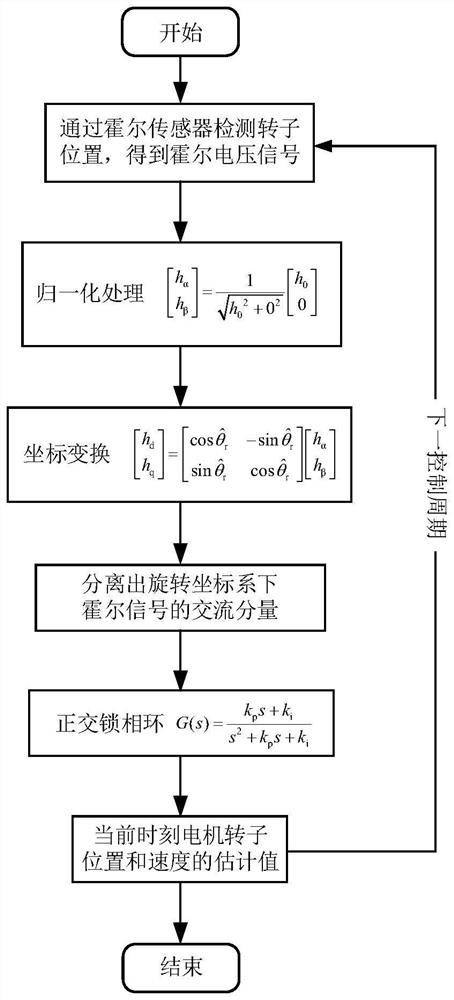
The invention discloses a permanent magnet synchronous motor rotor position and speed detection method based on an orthogonal phase-locked loop, and aims to solve the problem of high requirements on rotor position and speed signal precision in vector control of a permanent magnet synchronous motor by utilizing a detection signal of a single linear Hall sensor based on a positive and negative sequence component separation thought. The method comprises the following steps of: extracting a positive sequence component in a single linear Hall sensor detection signal under a rotating coordinate system by utilizing the characteristic that a positive sequence component and a negative sequence component in a Hall signal respectively represent an alternating current quantity and a direct current quantity under the rotating coordinate system, and synchronizing phases between an output signal and an input signal through an orthogonal phase-locked loop; therefore, zero-static-error tracking of an output rotor position estimation value on an input signal phase is realized, and rotor position and speed detection of the permanent magnet synchronous motor is realized. According to the method, the problem that amplitude deviation and phase deviation exist among a plurality of Hall signals in a traditional rotor position detection scheme of the permanent magnet synchronous motor is well solved, the algorithm implementation and the system structure are simple, and the robustness is high.

Description

technical field [0001] The invention relates to a permanent magnet synchronous motor rotor position and speed detection technology, in particular to a permanent magnet synchronous motor rotor position and speed detection method based on a quadrature phase-locked loop. Background technique [0002] Permanent magnet synchronous motors have the advantages of high efficiency, high power factor and reliable operation, and are widely used in industrial production, aerospace and household appliances. In the vector control of permanent magnet synchronous motor, the accuracy of rotor position and speed signal is relatively high, and the control system needs to obtain rotor position information in real time. From the perspective of adaptability to various working conditions, the current use of mechanical sensors is to obtain permanent magnet synchronous motor The most reliable solution for rotor position information. [0003] Hall sensors have the advantages of small size, simple str...

Claims


Application Information

Patent Timeline
Patent Type & Authority Applications(China)
IPC IPC(8): H02P21/14H02P21/18H02P25/022
CPCH02P21/14H02P21/18H02P25/022H02P2207/05
Inventor 王晓琳韩冰阳甘强司徒安祺
Owner NANJING UNIV OF AERONAUTICS & ASTRONAUTICS
Learn More