


Quick Research
Generate reliable direction feasibility study reports for your R&D in just a few steps.

Technical Q&A
Discover and master advanced knowledge NOW. Basics, ideas, possibilities, all at once.

Find Solutions
As an expert in R&D theories, this can generate solutions to your technical problems instantly.

Evaluate Feasibility
Analyze your overall solution with one click, know your potential R&D risks in advance.

Monitor Landscape
Get weekly tech updates, stay abreast of the latest tech innovations and key insights.
Shield tunneling machine hob abrasion positioning detection device
A positioning detection device and technology of shield machine, applied in the field of shield machine, can solve the problems of inability to provide wear degree, influence on site construction environment, investment of huge money cost and time cost, etc.
- Summary
- Abstract
- Description
- Claims
- Application Information
AI Technical Summary
Problems solved by technology
Method used
Image

Examples
Embodiment 1
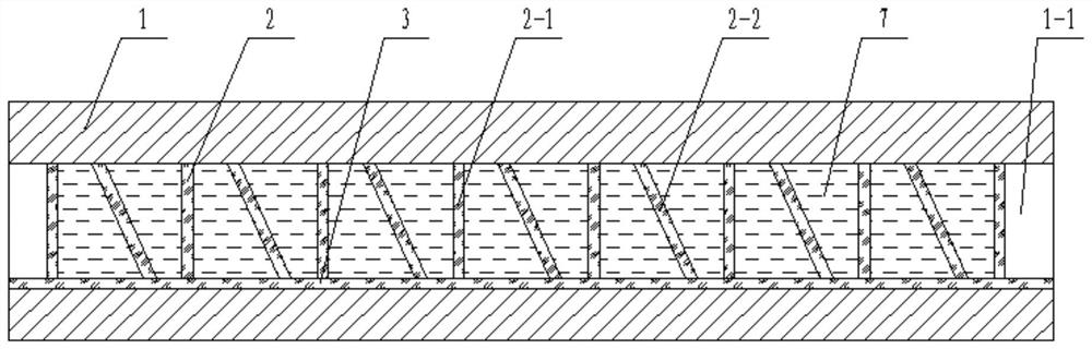
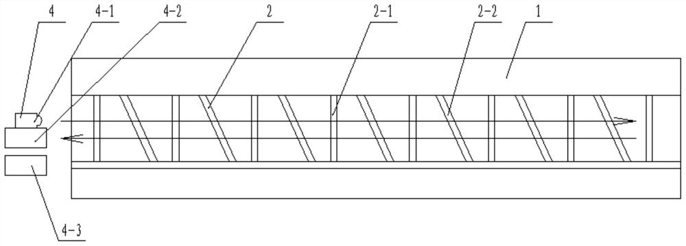
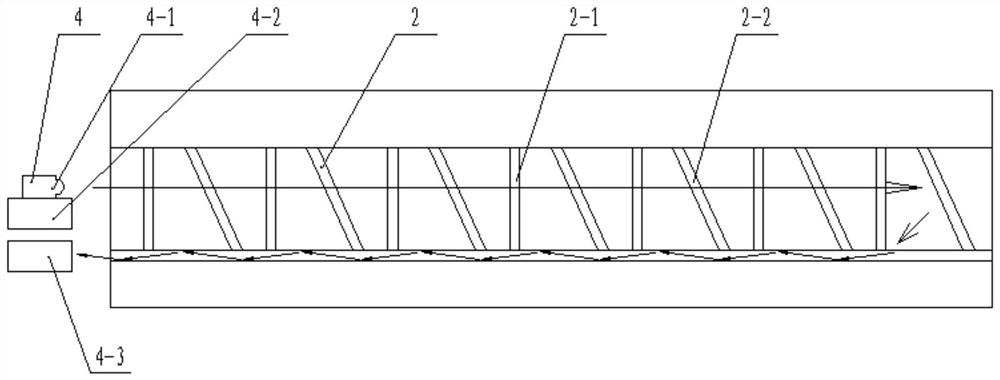
[0041] This embodiment provides a shield machine hob wear and positioning detection device, such as figure 1 and Figure 4As shown, it includes at least one base body 1 and a detection assembly, the base body 1 is provided with an installation channel 1-1, and the detection assembly includes an optical transceiver module 4 and a reflector, and the reflector is regularly arranged in the installation channel 1-1 1, the optical transceiver module 4 includes a emitting element 4-1 and a plurality of receiving elements, the reflector is a transparent material, a filling liquid 7 is arranged between adjacent reflectors, and the refractive index of the filling liquid 7 The same as the refractive index of the reflector, when the detection light emitted by the optical transceiver module 4 passes through the reflector and the filling liquid 7, since the refractive index of the reflector and the filling liquid are similar, as long as it is inscribed within the setting error, the detectio...
Embodiment 2
[0048] like Figure 8-9 As shown in the figure, compared with the first embodiment, the main difference of this embodiment is that the form of the reflector used is different, the reflector used in this embodiment is the corner plate 5, and the corner plate 5 is composed of two flat reflectors , there is a certain angle between the two reflective plates. Same as the first embodiment, the corner plate 5 is also made of transparent material, and all the corner plates 5 are also arranged in the installation channel 1-1 according to a certain rule. The vertical angle The plate 5-1 and the horizontal corner plate 5-2 are arranged at intervals, and a filling liquid 7 is arranged between the adjacent corner plates. The positions of the reflected light of the vertical corner plate 5-1 and the horizontal corner plate 5-2 are different, corresponding to There are two receiving elements, the first receiving element 4-2 is used to receive the reflected light of the vertical gusset 5-1, th...
Embodiment 3
[0051] like Figure 11 As shown, compared with the first embodiment, the main difference of this embodiment is that the form of the reflector used is different, the reflector used in this embodiment is the polarizer 6, and the same as the above is that the polarizer The state of 6 is the horizontal polarizer 6-1 and the vertical polarizer 6-2, all polarizers are arranged in parallel, but the deflection angles of the horizontal polarizer 6-1 and the vertical polarizer 6-2 are different, that is, the horizontal polarizer The polarization angles of the plate 6-1 and the vertical polarizer 6-2 are different, the vertical polarizer 6-2 and the vertical polarizer 6-2 are alternated, and a filling liquid 7 is arranged between the adjacent polarizers, and the The detection light is point-shaped, and after being reflected by the polarized light at the end, the reflected light is called an ellipse, such as Figure 12 Shown is the reflected light spot of vertical polarizer 6-2, as ima...
PUM
 Abstract
Description
Claims
Application Information
 - R&D Engineer
- R&D Manager
- IP Professional
- Industry Leading Data Capabilities
- Powerful AI technology
- Patent DNA Extraction
Browse by: Latest US Patents, China's latest patents, Technical Efficacy Thesaurus, Application Domain, Technology Topic, Popular Technical Reports.
© 2024 PatSnap. All rights reserved.Legal|Privacy policy|Modern Slavery Act Transparency Statement|Sitemap|About US| Contact US: help@patsnap.com