Brake chamber and method for detecting braking action relief of brake chamber

A technology of brake air chamber and braking action, applied in the direction of hydraulic brake transmission device, brake safety system, etc., can solve the problems of parking brake not being released, push rod pushing out, pipeline bending, etc., to achieve comprehensive Detection and accurate judgment, not easy to damage, avoid the effect of misjudgment

Inactive Publication Date: 2016-10-12
XUZHOU HEAVY MASCH CO LTD
View PDF7 Cites 0 Cited by
  • Summary
  • Abstract
  • Description
  • Claims
  • Application Information

AI Technical Summary

Problems solved by technology

[0009] 1. The hand brake valve has air pressure, and it reaches the specified value, but there is a bending phenomenon on the pipeline between the hand brake valve and the parking brake air chamber, and the air pressure is different, so in fact, the pressure of the brake air chamber The push rod is not pushed out by air pressure, so the actual parking brake is not released
[0010] 2. If the brake spring in the brake air chamber is stuck, even if the air pressure in the parking brake air chamber reaches a certain value, the push rod cannot be pushed out, so the parking brake is not actually released.
[0011] 3. Failure of other intermediate links will also cause misjudgment
[0012] At the same time, there will be misjudgment of the driving brake
[0013] Therefore, before the vehicle starts, when the parking brake is not released after the hand brake is released, it will cause difficulty in starting the vehicle and brake wear and other phenomena will occur; Will cause brake wear and other phenomena to occur

Method used


Image

  • Brake chamber and method for detecting braking action relief of brake chamber
  • Brake chamber and method for detecting braking action relief of brake chamber

Examples


Embodiment 1

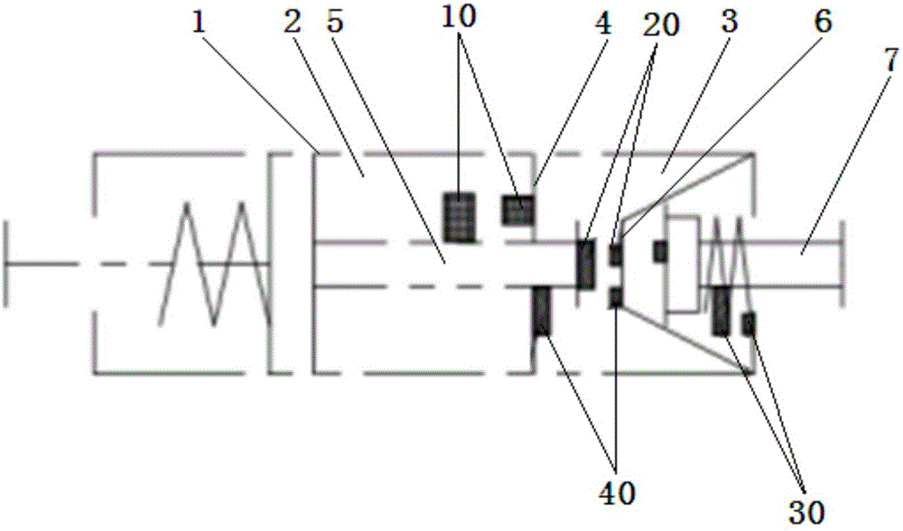
[0039] Such as figure 1 The shown brake air chamber is an energy storage spring brake air chamber, which includes a first housing 1, a parking brake air chamber 2 located in the first housing 1 and a first service brake air chamber 3 located in The partition 4 between the parking brake chamber 2 and the first service brake chamber 3, the push rod 5 passing through the partition 4, and the first diaphragm 6 and the first diaphragm 6 located in the first service brake chamber 3 A push rod 7; the front end of the push rod 5 is located in the first service brake air chamber 3, and keeps a distance from the first diaphragm 6; the rear end of the push rod is located in the parking brake air chamber 2; the first A push rod 7 passes through the first casing 1 .

[0040] The energy storage spring brake air chamber can realize both service braking and parking braking.

[0041] Parking brake test for stored-energy spring brake chambers:

[0042] 1) The first position detection device ...

Embodiment 2

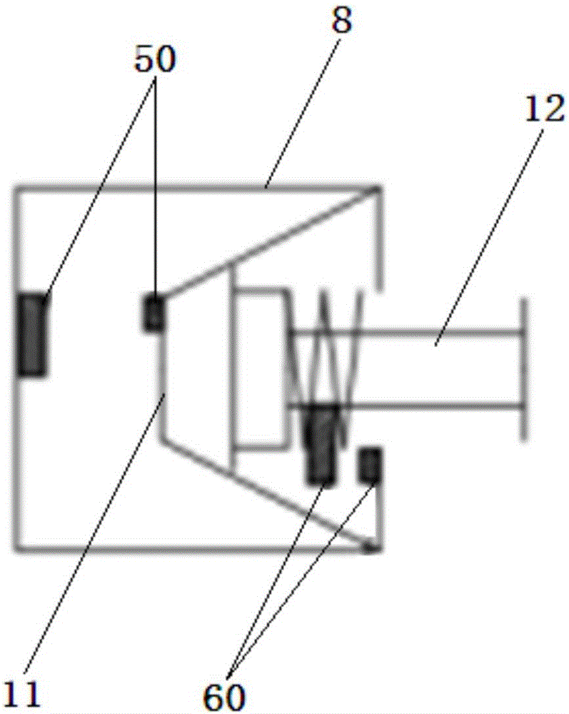
[0052] Such as figure 2 The brake air chamber shown is a diaphragm brake air chamber, which includes a second housing 8, a second service brake air chamber 9 located in the second housing 8, and a second service brake air chamber 9 located in the second housing 8. The second diaphragm 11 and the second push rod 12 inside; the second push rod 12 passes through the second casing 8 .

[0053] The diaphragm brake air chamber can only realize service braking, and its service brake detection is:

[0054] 1) A fifth position detection device 50 is installed in the second service brake air chamber 9 , and the probe and the sensing plate of the fifth position detection device 50 are arranged in pairs on the rod body of the second ejector rod 12 of the second service brake air chamber 9 On the position facing the second housing 8, to detect the third extension distance that the second push rod 12 of the second service brake air chamber 9 extends out of the second service brake air cha...


PUM


Abstract

The invention discloses a method for detecting braking action relief of a brake chamber. A position detection device is arranged in the brake chamber and is used for detecting if the mechanical action of the brake chamber is properly executed so as to judge if the braking action is truly relieved; when the position detection device detects that the mechanical action of the brake chamber is properly executed, the braking action is confirmed as being truly relieved; when the position detection device detects that the mechanical action of the brake chamber is not properly executed, the braking action is confirmed as being not truly relieved. The detection method provided by the invention is modified on the basis of the brake chamber; specifically, the position detection device is arranged in the brake chamber; an executing position of a braking executing mechanism (such as ejector rod and push rod) of the brake chamber is detected and accuratelyjudged, and then a driver is helped to judge if a parking brake is truly relieved after hand brake is released and if the travelling brake is truly relieved after foot brake is released; the detecting method belongs to direct detection and can be adopted for realizing accurate judgment and preventing erroneous judgment.

Description

technical field [0001] The invention relates to a braking detection method, in particular to a detection method for releasing the braking effect of a brake air chamber and the brake air chamber, belonging to the technical field of vehicle braking systems. Background technique [0002] At present, according to the transmission mode of braking energy, the braking system can be divided into mechanical braking, hydraulic braking, pneumatic braking, electromagnetic braking and combined braking. 1) Mechanical brake: The mechanical brake device is composed of purely mechanical parts and is generally used for parking brake; 2) Hydraulic brake: The hydraulic brake device uses hydraulic oil to convert the force of the brake pedal into hydraulic pressure, and through the pipe The road is transmitted to the wheel brake, and then the hydraulic pressure is converted into mechanical force for braking; 3) Pneumatic braking: the pneumatic braking device uses compressed air as a power source,...

Claims


Application Information

Patent Timeline
IPC IPC(8): B60T17/22B60T11/10
CPCB60T17/22B60T11/10
Inventor 王厚胜马云旺吴恒昌靳少杰贾东亮
Owner XUZHOU HEAVY MASCH CO LTD
Why Eureka
Try Eureka