Flexible telescopic drill rod mechanism special for leap device
A telescopic drill pipe and flexible technology, applied to drill pipes, rotary drilling rigs, drill pipes, etc., can solve the problems of difficult underground exploration in lunar soil, large detectors that are inconvenient to land, etc., and achieve stable and space-saving process of footage and tapering. The effect of high utilization rate and low power consumption of shoveling
- Summary
- Abstract
- Description
- Claims
- Application Information
AI Technical Summary
Problems solved by technology
Method used
Image
Examples
specific Embodiment approach 1
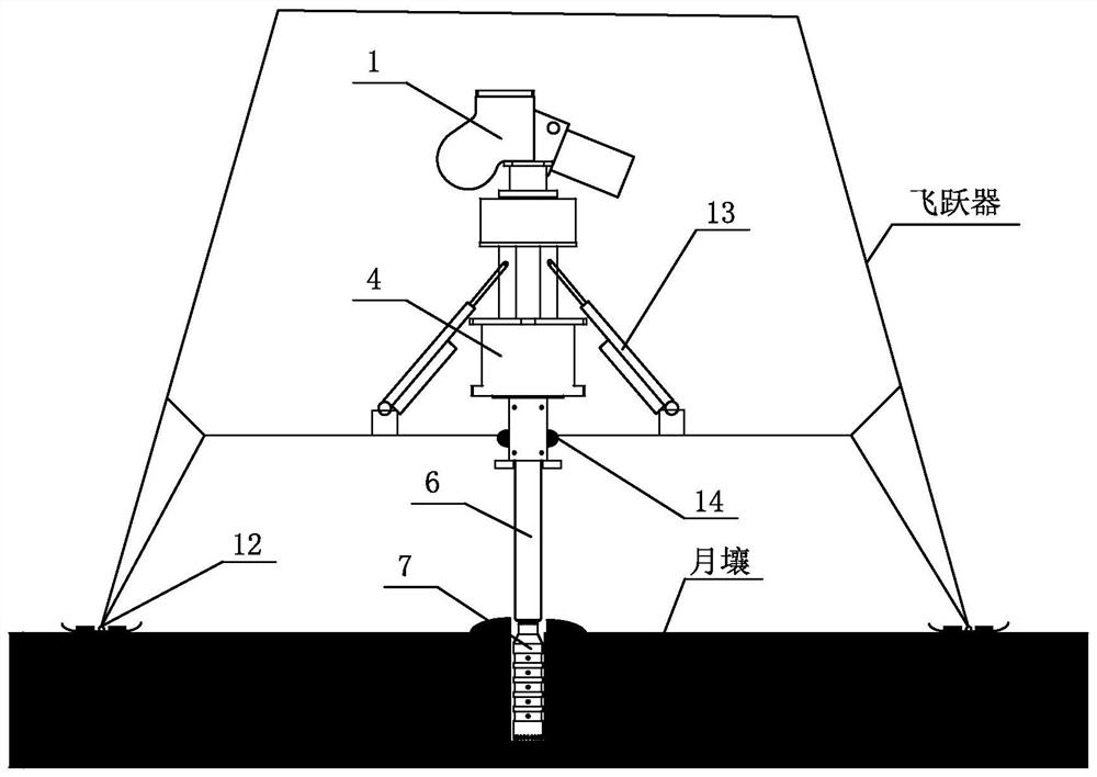
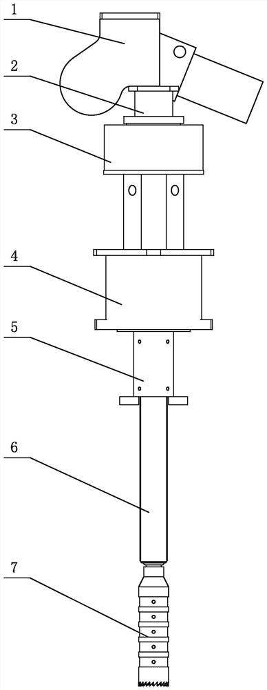
[0031] Embodiment 1: Combining Figure 1 to Figure 12 This embodiment will be described. The flexible telescopic drill rod mechanism dedicated to the leaper described in this embodiment includes a flexible probe driver 1, a drilling system and an electric push rod 13; the flexible probe driver 1 is installed on the upper part of the drilling system, The drilling system is installed on the leaper, one end of the electric push rod 13 is hinged with the drilling system, and the other end is hinged with the leaper. Together with the multi-stage telescopic drill pipe 6 in the drilling system, the movement of the leaper and the sampling of lunar soil are completed.
[0032] In the lunar soil exploration and sampling work, due to the high launch cost and strict quality requirements, the lunar soil exploration and sampling equipment is required to have the characteristics of high integration, high reliability and light weight. It transmits torque to the drill pipe, reduces the energy...
specific Embodiment approach 2
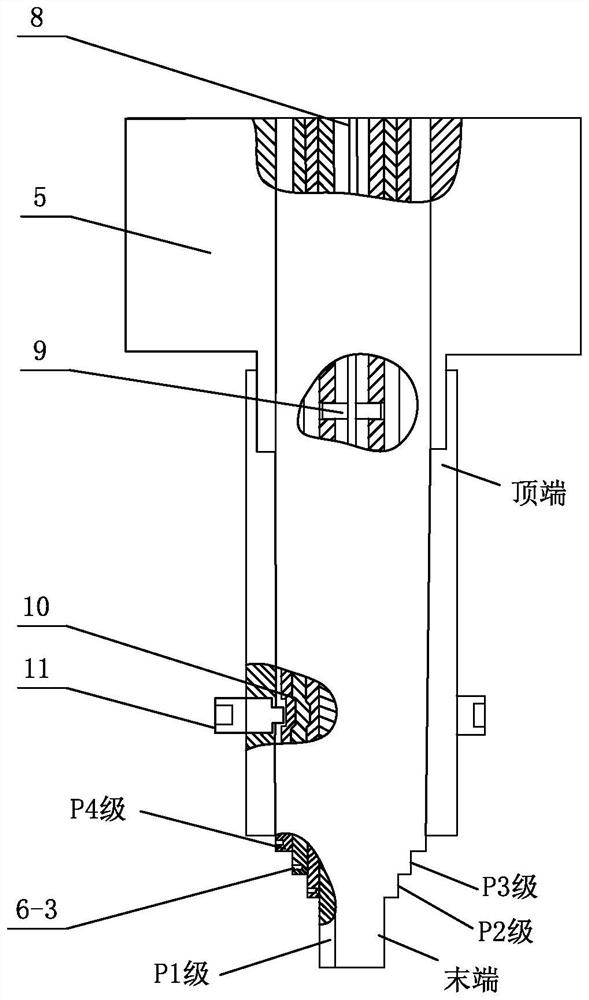
[0033] Specific implementation mode 2: Combining Figure 1 to Figure 12 Illustrating this embodiment, the drilling system in this embodiment further includes a front guide rod 2, a guide sleeve 5 and a helical coring bit 7; the front guide rod 2 is a hollow structure, and one end of the front guide rod 2 and The flexible probe driver 1 is connected, and the other end is connected with the hollow rotary motor 4. The guide sleeve 5 is a hollow structure. One end of the guide sleeve 5 is connected with the rotor of the hollow rotary motor 4 through the connecting pin 9, and the other end is connected The helical coring drill bit 7 is connected with the multi-stage telescopic drill rod 6 by connecting with the screw and the multi-stage telescopic drill rod 6 .
[0034] In this embodiment, an electric slip ring 3 is installed on the upper part of the hollow rotary electric machine 4 , and the electric slip ring is responsible for communicating and conveying energy and signals for t...
specific Embodiment approach 3
[0036] Specific implementation three: combination Figure 1 to Figure 12 Illustrating this embodiment, the flexible probe driver 1 described in this embodiment includes a coil spring shaft 1-2, a flexible probe steel belt 1-3, and an active friction wheel 1- 4 and the driven friction wheel 1-5; the flexible probe driver housing 1-1 is connected with the front guide rod 2, the scroll spring shaft 1-2, the driving friction wheel 1-4 and the driven friction wheel 1-5 are all rotatably connected to the inner wall of the flexible probe drive housing 1-1, and one end of the flexible probe steel belt 1-3 is wound and connected to the coil spring shaft 1-2, and then passes through the active friction wheel 1- 4 and the pre-tightening of the driven friction wheels 1-5, the other end is connected to the multi-stage telescopic drill rod 6 through the front guide rod 2, the rotor of the hollow rotary motor 4 and the guide sleeve 5 in turn.
[0037] In this embodiment, the active friction...
PUM
 Abstract
Description
Claims
Application Information
 - Generate Ideas
- Intellectual Property
- Life Sciences
- Materials
- Tech Scout
- Unparalleled Data Quality
- Higher Quality Content
- 60% Fewer Hallucinations
Browse by: Latest US Patents, China's latest patents, Technical Efficacy Thesaurus, Application Domain, Technology Topic, Popular Technical Reports.
© 2025 PatSnap. All rights reserved.Legal|Privacy policy|Modern Slavery Act Transparency Statement|Sitemap|About US| Contact US: help@patsnap.com


